MATLAB Command Line
Click to copy the following command line to the clipboard. Then paste it in the MATLAB Command Window:
edit hil_analog_loopback_example.mHIL Analog Loopback Example
This example is a simple analog loopback test, but it demonstrates an important features of the QUARC MATLAB functions - the ability to read and write from a device at a specified rate in a single function call. This feature is particularly useful for system identification, in which the relative timing between the input and output signals is important.
System Requirements
This example requires hardware supported by the HIL command set, such as the Q4 or Q8 hardware-in-the-loop card. Furthermore, the card must support simultaneous read and write buffered operations.
Configuring the example
To set up the example for your data acquisition card, edit the M-file and change
the board_type to the type of board being used. If you have more than
one of these data acquisition cards in your machine, then also change the board_identifier
variable to refer to desire board. Board identifiers are typically equal to the
board number, with the first board being board '0', the next board being board '1',
etc.
Now wire analog output channels 0-3 to analog input channels 0-3. For the Q4 and
Q8 hardware-in-the-loop cards, simply connect an RCA cable from analog outputs 0-3
to analog inputs 0-3 on the terminal board. For boards supporting fewer channels,
change the input_channels and output_channels variables
accordingly.
Running the example
Simply type the name of the example, hil_analog_loopback_example,
at the Matlab command prompt to run the example. It will run for 0.5 seconds and
then show a sequence of plots to illustrate the collected data.
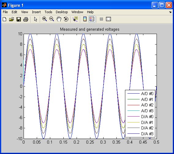
The first plot shows the data collected, as shown in the figure below.
Press Enter to display the next plot, which magnifies the beginning of the plot to illustrate that the A/D reading for the first sample reflects the initial value written to the D/A outputs of 5V, and subsequent A/D samples reflect the output written to the D/A outputs in the previous sample.
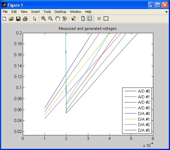
Press Enter once more to shift the A/D readings by one sample so that they overlap the D/A output values that they measure. This last plot looks similar to the first plot, of course, since the sample time is only 0.1 millisecond. This final plot completes the example.
Building code from the example
To build real-time code from the example for the QUARC Win64 target, execute the following command in the MATLAB Command Window:
qc_build_script('hil_analog_loopback_example', 'win64');
The command may also be entered in this form:
qc_build_script('hil_analog_loopback_example.rt-win64');
The qc_build_script command generates a build script called 'hil_analog_loopback_example_build.m'
and a main C file called 'hil_analog_loopback_example_main.c'. It then invokes the build script to
generate C code for the MATLAB script and to compile and link it into a QUARC executable called 'hil_analog_loopback_example.rt-win64'.
Running qc_build_script again will not overwrite the generated files, so they may be modified and
the changes will be incorporated when qc_build_script is run again.
Running the generated executable
Before running the generated executable, open a QUARC Console so that the output of the executable may be seen. The QUARC Console need only be opened once. Use the command:
qc_script_console('hil_analog_loopback_example.rt-win64', 'all');
The QUARC Console shows the standard output from any QUARC executable that is run on the target (since the 'all' option was specified).
To run the generated executable, type the following command in the MATLAB Command Window:
qc_run_script('hil_analog_loopback_example.rt-win64');
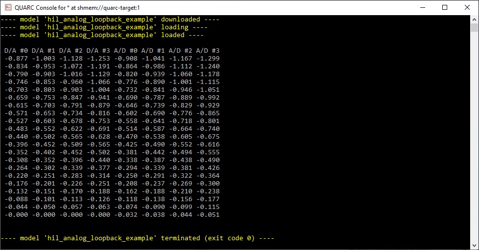
The output from the executable will be seen in the QUARC Console:
Copyright ©2026 Quanser Inc. This page was generated 2026-05-13. Submit feedback to Quanser about this page.
Link to this page.