MATLAB Command Line
Click to copy the following command line to the clipboard. Then paste it in the MATLAB Command Window:
quarc_multiwii_demoQUARC Multiwii Demo
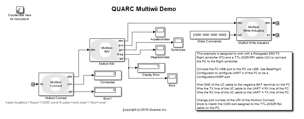
This example demonstrates how to use the Multiwii blocks from the QUARC Targets Library to communicate with a flight controller that supports the Multiwii Serial Protocol (MSP). For a detailed description of the Multiwii blocks and how they operate, please refer to the Multiwii Communications section of the QUARC documentation.
Configuring the Demonstration
This demonstration is designed to work with a Rotogeeks SSD F3 flight controller. The flight controller should be connected to the PC via a USB to USB cable, as well as a TTL-232R-RPi USB to serial cable. The TTL-232R-RPi cable converts from USB to 3.3V serial, which is important to prevent damaging the flight controller as standard USB to serial cables tend to output 5V serial.
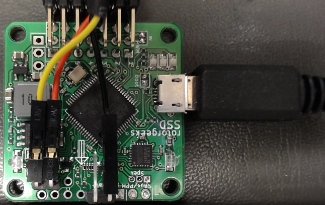
Before connecting the USB to serial cable, use Betaflight Configurator to configure UART4 of the Rotogeeks SSD F3 flight controller to be a Configuration/MSP port. Then connect the ground (black) of the USB to serial cable to the negative BAT terminal of the flight controller. Connect the Tx line of the USB to serial cable to the UART 4 RX line of the flight controller. Finally, connect the Rx line of the USB to serial cable to the UART 4 TX line of the flight controller. The connections are pictured below:
To set up the model, double-click on the Multiwii Connect block in the quarc_multiwii_demo.mdl model. Change the port number of the serial URI to match the COM port number assigned to the USB to serial cable. Use Device Manager under the Ports category to determine the COM port number of the USB Serial Port.
Demonstration
Select from the menu of the diagram, or press Ctrl+B while the diagram is the active window. A great deal of output will appear in the Diagnostic Viewer about the progress of the build. If you cannot see the Diagnostic Viewer, you can open it by selecting from the menu of the diagram, or clicking on the View Diagnostics hyperlink at the bottom of the diagram.
Double-click on the "Accelerometer" and "Gyroscope" Scope blocks in the model.
Click on the button or select from the menu of the diagrams to connect to the model.
Start the model by clicking on the button or selecting from the menu of the diagram. The item of the menu may also be used to both connect and start the model in one operation.
As the model runs, move the flight controller. The movements should register in the "Accelerometer" and "Gyroscope" plots. Changing the values of the "Motor Commands" Constant block should also alter the PWM outputs of the Rotogeeks flight controller. The values should range from 1000 to 2000 because the selected units are microseconds.
Click on the button or select from the menu of the diagram to stop each model. The item of the menu may also be used.
Copyright ©2026 Quanser Inc. This page was generated 2026-05-13. Submit feedback to Quanser about this page.
Link to this page.