
Quanser CubeSat CPP
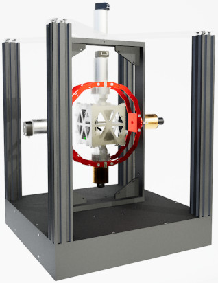
The Quanser CubeSat CPP is a 3-DOF gyroscope built by Quanser Inc for testing CubeSat satellites. The QUARC Target associated with the Quanser CubeSat CPP is the QUARC Linux Pi ARM64 Target. The CubeSat CPP driver provides access to the hardware I/O available on the CubeSat CPP platform. The CubeSat CPP platform includes a Raspberry Pi 5 compute module and base board with an ARM Cortex-A76 processor (2.4 GHz, four core, 64 bit) as well as a VideoCore VII GPU and additional I/O. The additional I/O includes:
The QUARC driver name for this card is cubesat_cpp. The latest operating system installed on the Quanser CubeSat CPP is the 64-bit Raspbian O/S.
To select the Quanser CubeSat CPP board, select the QUARC cubesat_cpp board type from the drop-down list on the Main tab of the HIL Initialize block. Please note that only one Quanser CubeSat CPP card can be connected and is supported in the system. The QUARC controller runs on the Pi 5 compute module.
| Note that the Linux Pi Arm64 target must be selected to use the Quanser CubeSat CPP board, as it is connected to the Pi 5 compute module. |
The Quanser CubeSat CPP supports three different means of communicating with it as a target. It supports wireless (WiFi) communications, which are most readily configured initially via the WiFi router web interface. Once configured, it should reconnect automatically whenever the WiFi signal is available.
The Quanser CubeSat CPP also supports a 10/100/1000 Mbps wired LAN connection. In the case of WiFi or LAN the IP address is determined by the adapter settings. Typically, the IP address is assigned dynamically by a DHCP server on the network.
Communications
The communications ports provided on the Quanser CubeSat CPP board can be utilized through the QUARC Communications blockset and the Quanser Stream API (see QUARC Communications Protocols).
SPI
For SPI communications, a sample URI for communications would be:
spi://localhost:0?baud='1000000',polarity='off',phase='off',lsb='off',frame='0'
where the frame option selects the SPI SS line to frame the SPI bus transaction (0).
It supports baud rates up to 125 MBaud, although signal integrity may limit it to slower rates closer to 30 Mbaud.
I2C
For I2C communications, a sample URI for communications would be:
i2c://localhost:0?baud='100000',address=0x69
where the address option specifies the I2C slave address.
Serial
For serial communications, a sample URI for communications would be:
serial://localhost:0?baud='115200',word='8',parity='none',stop='1'
It supports baud rates up to 3 MBaud.
Summary
The communications channels are summarized in the table below:
|
Protocol |
Port |
Label |
Sample URI |
Comments |
|---|---|---|---|---|
|
i2c |
0 |
I2C0 |
i2c://localhost:0?baud=100e3,address=0x6B |
Baud rate is fixed at 100 kHz, unless reconfigured in the config.txt file. |
|
serial |
0 |
UART0 |
serial://localhost:0?baud=115200,parity=none,stop=1,flow=none |
Includes hardware flow control signals RTS and CTS |
|
spi |
0 |
SPI0 |
spi://localhost:0?baud=10000000,polarity=off,phase=off,lsb=off,frame=0 |
Supports one chip select only (0). |
Clocks
The Quanser CubeSat CPP card does not support hardware clocks.
Analog Inputs
The Quanser CubeSat CPP driver supports 4 analog inputs. Hence, analog input channel numbers range from 0 to 3.
The user 3.3V supply current is reported at analog input channel 0 in Amperes. Channel 1 is the supply voltage in Volts. Channel 2 is the user 5V supply current in Amperes and channel 3 is the user 12V supply current in Amperes.
Analog Outputs
The Quanser CubeSat CPP card does not support analog outputs.
Digital Inputs
The Quanser CubeSat CPP supports 10 bidirectional digital I/O lines, as well as three magnetometer overflow condition indicators (X, Y, Z) which act as digital inputs. Hence digital input channel numbers range from 0 to 12. A digital I/O line cannot be used as an input and output at the same time.
| All digital channels are 3.3V. |
The first 10 digital I/O lines may be individually programmed as inputs or
outputs on the Quanser CubeSat CPP. All of those 10 channels which will be used for digital inputs
should be configured on the HIL Initialize
block's Digital Inputs tab. Set the Digital input channels field to all
the digital I/O channels that will be used as digital inputs on the board for the current diagram. For example, enter
0:3 to designate channels 0 through 3 as digital inputs. Specify
[0, 4, 5] to indicate that channels 0, 4 and 5 are to be configured
as digital inputs.
Digital Outputs
The Quanser CubeSat CPP supports 10 bidirectional digital I/O lines and four power enables. Hence digital output channel numbers range from 0 to 13. A digital I/O line cannot be used as an input and output at the same time. The four power enables are for the user 3.3V, user 5V, user 12V and active markers respectively.
| All the digital channels are 3.3V. |
Since the first 10 digital I/O lines may be individually programmed as inputs or outputs
on the Quanser CubeSat CPP, all the channels which will be used for digital outputs should be configured
on the HIL Initialize block's
Digital Outputs tab. Set the Digital output channels
field to all the bidirectional digital I/O channels that will
be used as digital outputs on the board for the current diagram. For example, enter
0:3 to designate channels 0 through 3 as digital outputs. Specify
[0, 4, 5] to indicate that channels 0, 4 and 5 are to be configured
as digital outputs.
To set the digital output values when the model is loaded or unloaded, set the Initial digital outputs and Final digital outputs to the desired values respectively. If the vectors specified in these fields are shorter than the channel vector, the value of the last element in the vector will be used for the rest of the channels. Hence, a scalar value will apply to all channels specified in the Digital output channels field.
Encoder Inputs
The Quanser CubeSat CPP card does not support encoder inputs.
PWM Outputs
The Quanser CubeSat CPP card does not support PWM outputs.
Other Inputs
The specific Other Input channels of the Quanser CubeSat CPP board are described in the table below. SI units are used.
|
Other Input Channel |
Measurement Description |
Units |
|---|---|---|
|
3000, 3001, 3002 |
Angular velocity around the x-, y-, and z-axis, respectively (from gyroscope) |
(rad/s) |
|
4000, 4001, 4002 |
Linear acceleration along the x-, y-, and z-axis, respectively (from accelerometer) |
(m/s2) |
|
8000, 8001, 8002 |
Magnetic fields along the x-, y-, and z-axis, respectively (from magnetometer) |
(T) |
|
10000 |
Temperature of IMU sensor. |
(C) |
|
10001 |
Temperature of magnetometer sensor. |
(C) |
Channel numbers for Other Input or Output channels use predefined ranges for each type of measurement to ensure consistency between data acquisition devices. Refer to QUARC Other Channels for a list of the Other Input or Output channel number ranges defined for any HIL Data Acquisition Card and their SI units.
Note that the IMU may be read at any time, but measurements are updated internally at a fixed 32 kHz rate. The gyroscope and accelerometer can produce new values at this rate. The output data rate for the different IMU components may be set in the board-specific options (see below).
Other Outputs
The Quanser CubeSat CPP card does not support other outputs.
Interrupts
The Quanser CubeSat CPP card, or its driver, does not support any interrupt sources.
Watchdog
The Quanser CubeSat CPP card does not support a watchdog timer.
Board-Specific Options
The Quanser CubeSat CPP has a number of board-specific options to control specialized functionality of the Quanser CubeSat CPP. These options configure the IMU and magnetometer.
gyro_fs
This option sets the full-scale range of the gyroscope sensor. Valid values range from 125 to 2000. The units are degrees per second.
gyro_rate
This option sets the gyroscope sensor's sampling rate. Valid values range from 12.5 to 32000. The units are Hz.
gyro_ord
This option sets the gyroscope sensor's filter order. Valid values range from 1 to 3.
gyro_bw
This option sets the gyroscope sensor's filter bandwidth. Valid values range from 6.25 to 32000. The units are Hz.
accel_fs
This option configures the full-scale range of the accelerometer. Valid values are 2 to 16. The units are g's.
accel_rate
This option sets the accelerometer's sampling rate. Valid values range from 12.5 to 32000. The units are Hz.
accel_ord
This option sets the accelerometer sensor's filter order. Valid values range from 1 to 3.
accel_bw
This option sets the accelerometer sensor's filter bandwidth. Valid values range from 6.25 to 32000. The units are Hz.
imu_temp_bw
This option sets the IMU temperature sensor's filter bandwidth. Valid values range from 5 to 4000. The units are Hz.
mag_os
This option configures the oversampling of the magnetometer X, Y and Z axes. Valid values are 32 or 64.
mag_xy_fs
This option configures the full-scale range of the X and Y axes of the magnetometer. Valid values are 25 or 50. The units are mT's.
mag_z_fs
This option configures the full-scale range of the Z axis of the magnetometer. Valid values are 25, 50, 100 or 200. The units are mT's.
mag_rate
This option sets the magnetometer's sampling rate. Valid values range from 10 to 1400. The units are Hz.
mag_xy_bw
This option sets the magnetometer sensor's filter bandwidth for the X and Y axes. Valid values range from 145.21 to 8849.5 when 32x oversampling is used. Valid values range from 72.64 to 4545.4 when 64x oversampling is used. The units are Hz.
mag_z_bw
This option sets the magnetometer sensor's filter bandwidth for the Z axis. Valid values range from 145.21 to 8849.5 when 32x oversampling is used. Valid values range from 72.64 to 4545.4 when 64x oversampling is used. The units are Hz.
mag_temp_en
This boolean option enables or disables the magnetometer's temperature sensor. When the temperature sensor is enabled then temperature compensation is used.
mag_temp_os
This option configures the oversampling of the magnetometer temperature sensor. Valid values are 32 or 64.
mag_temp_bw
This option sets the magnetometer temperature sensor's filter bandwidth. Valid values range from 145.21 to 8849.5 when 32x oversampling is used. Valid values range from 72.64 to 4545.4 when 64x oversampling is used. The units are Hz.
Properties
The Quanser CubeSat CPP supports the following integer properties:
|
Property Name |
Property Code |
Description |
|---|---|---|
|
PROPERTY_INTEGER_NUMBER_OF_ANALOG_INPUTS |
16 |
The number of analog input channels. |
|
PROPERTY_INTEGER_NUMBER_OF_ENCODER_INPUTS |
17 |
The number of encoder input channels. |
|
PROPERTY_INTEGER_NUMBER_OF_DIGITAL_INPUTS |
18 |
The number of potential digital input channels. |
|
PROPERTY_INTEGER_NUMBER_OF_OTHER_INPUTS |
19 |
The number of other input channels. |
|
PROPERTY_INTEGER_NUMBER_OF_ANALOG_OUTPUTS |
20 |
The number of analog output channels. |
|
PROPERTY_INTEGER_NUMBER_OF_PWM_OUTPUTS |
21 |
The number of PWM output channels. |
|
PROPERTY_INTEGER_NUMBER_OF_DIGITAL_OUTPUTS |
22 |
The number of potential digital output channels. |
|
PROPERTY_INTEGER_NUMBER_OF_OTHER_OUTPUTS |
23 |
The number of other output channels. |
|
PROPERTY_INTEGER_NUMBER_OF_CLOCKS |
24 |
The number of clocks. |
|
PROPERTY_INTEGER_NUMBER_OF_INTERRUPTS |
25 |
The number of interrupt channels. |
Connectors
The Quanser CubeSat CPP board has a number of connectors for expansion I/O. These connectors and their pinouts are listed below.
| Note that all pins are 3.3V and are not 5V tolerant. |
J2 Connector
Ground ― | 24 | 23 | ― Ground |
D9 (GPIO27) ↔ | 22 | 21 | → UART RTS |
D8 (GPIO26) ↔ | 20 | 19 | ← UART CTS |
D7 (GPIO25) ↔ | 18 | 17 | ← UART RX |
D6 (GPIO24) ↔ | 16 | 15 | → UART TX |
D5 (GPIO23) ↔ | 14 | 13 | → SPI SCLK |
D4 (GPIO22) ↔ | 12 | 11 | → SPI COPI |
D3 (GPIO21) ↔ | 10 | 9 | ← SPI CIPO |
D2 (GPIO20) ↔ | 8 | 7 | → SPI CS0 |
D1 (GPIO19) ↔ | 6 | 5 | ↔ I2C SCL |
D0 (GPIO18) ↔ | 4 | 3 | ↔ I2C SDA |
Ground ― | 2 | 1 | ― Ground |
Legend
→▯← | = | input |
←▯→ | = | output |
↔▯↔ | = | bidirectional I/O |
= | 3.3V signal | |
= | unspecified voltage | |
= | ground |
Targets
|
Target |
Supported |
Comments |
|---|---|---|
|
No |
Not supported. |
|
|
No |
Not supported. |
|
|
No |
Not supported. |
|
|
No |
Not supported. |
|
|
No |
Not supported. |
|
|
No |
Not supported. |
|
|
No |
Not supported. |
|
|
No |
Not supported. |
|
|
Yes |
Fully supported. |
|
|
No |
Not supported. |
|
|
No |
Not supported. |
|
|
No |
Not supported. |
|
|
No |
Not supported. |
|
|
No |
Not supported. |
|
|
No |
Last fully supported in QUARC 2018. |
|
|
Rapid Simulation (RSIM) Target |
Yes |
Supported with no communication to the hardware. |
|
Normal simulation |
Yes |
Supported with no communication to the hardware. |
Copyright ©2026 Quanser Inc. This page was generated 2026-05-13. Submit feedback to Quanser about this page.
Link to this page.
