
CEAL Staircase Force Plates
Outputs the forces and torques measured in SI units (i.e., N, N.m) from up to the four (4) AMTI force plates used in the Challenging Environment Assessment Laboratory (CEAL) instrumented staircase.
Library
QUARC Applications/CEAL/Devices/Third-Party/AMTI/Force Plates MATLAB Command Line Click to copy the following command line to the clipboard. Then paste it in the MATLAB Command Window: qc_open_library('quarc_library_applications/CEAL/Devices/Third-Party/AMTI/Force Plates')
Description
The CEAL Staircase Force Plates block outputs the forces and torques measured in S.I. units (i.e., N, N.m) from up to the four (4) AMTI force plates used in the Challenging Environment Assessment Laboratory (CEAL) staircase. The CEAL instrumented staircase consists of 8 steps with 7-inch risers and 11-inch runs. There are four AMTI force plates (specifically model BP250500-6-2000) available that can be installed under four of the treads. Each staircase force plate has a length of 0.5 m and a width of 0.25 m. The sensitivity matrix of each force plate is taken into account to calculate the measured forces and torques.
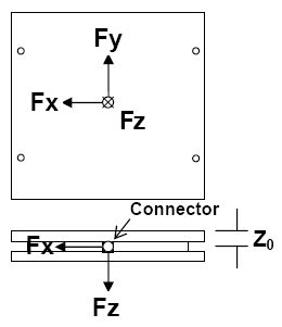
The Cartesian reference frame used is shown below.
Installation Requirements
Force Plate Connections
 Each of the four (4) AMTI force plates should be connected to the analog input channels
of the NI PCI-6255 card, as indicated in the table below.
Each of the four (4) AMTI force plates should be connected to the analog input channels
of the NI PCI-6255 card, as indicated in the table below.
|
Analog Inputs |
Force Plate Serial Number and Signals |
|---|---|
|
AI #0 to AI #5 |
SN 5072.1: Fx, Fy, Fz, Mx, My, Mz |
|
AI #6 to AI #11 |
SN 5073.1: Fx, Fy, Fz, Mx, My, Mz |
|
AI #16 to AI #21 |
SN 5074.1: Fx, Fy, Fz, Mx, My, Mz |
|
AI #22 to AI #27 |
SN 5075.1: Fx, Fy, Fz, Mx, My, Mz |
CEAL NI PCI-6255
The CEAL Staircase Force Plates block is meant to be used in conjunction with the
CEAL NI PCI-6255
block, which provides the appropriate interface to the National Instruments PCI-6255 card used by the CEAL.
Input Ports
This block has no input ports.
Output Ports
forces and torques
A 24-element vector of double values containing the force and torque data in SI units (i.e., m and N.m) for each one of the 4 force plates.
This output vector contains 4 sets of 6-element force/torque data, each ordered according to the user-selected plate location.
Step #1,
as selected using the drop-down menus of the Force Plates pane.
If this step location is not used, its corresponding 6-element set of force/torque values is set to zero.
Step #2,
as selected using the drop-down menus of the Force Plates pane.
If this step location is not used, its corresponding 6-element set of force/torque values is set to zero.
Step #3,
as selected using the drop-down menus of the Force Plates pane.
If this step location is not used, its corresponding 6-element set of force/torque values is set to zero.
Step #4,
as selected using the drop-down menus of the Force Plates pane.
If this step location is not used, its corresponding 6-element set of force/torque values is set to zero.
error
A uint8 value indicating, with a value of 1, whether two or more force plates have been assigned to the same step location on the staircase.
A value of 0 indicates no error with the step assignment.
Parameters and Dialog Box
Individual Panes
Each plate is uniquely identified by its Serial Number (SN), to which corresponds a unique sensitivity matrix.
Each staircase force plate uses a AMTI MSA-6 Strain Gage amplifier. It is assumed that all four force plate amplifiers (MSA) are tuned (in terms of their jumper configuration setting the 6 channel gains and the 6 channel excitation gains) the exact same way for all 4 force plates.
Force Plates Pane
The Force Plates pane of the dialog appears as follows:
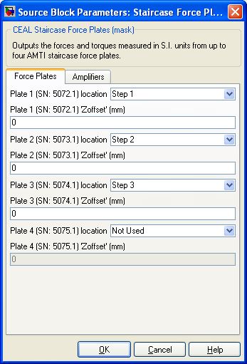
Plate 1 (SN: 5072.1) location (tunable online)
Plate 1 corresponds to the force plate whose serial number is: 5072.1. The 6 BNC cables for plate 1 (corresponding to the Fx, Fy, Fz, Mx, My, and Mz signals) must be connected to Analog Input #0 to Analog Input #5, respectively.
Select from this drop-down menu the step location ID, as previously defined, where force plate 1 is installed.
This selection determines where the measured set of 6 force/torque signals for plate 1
is located in the 24-element forces and torques output vector.
Plate 1 (SN: 5072.1) 'Zoffset' (mm) (tunable online)
The 'Zoffset' value for plate 1 is a negative number representing the thickness (in mm) along the 'Z' axis of any plate(s) mounted on top of plate 1. This offset value is used in addition to 'Z0' (i.e., the negative number representing the difference between plate 1 actual origin and the plate's top along the 'Z' axis) in order to shift the origin to calculate the correct Mx and My torques on the force plate's top surface.
Plate 2 (SN: 5073.1) location (tunable online)
Plate 2 corresponds to the force plate whose serial number is: 5073.1. The 6 BNC cables for plate 2 (corresponding to the Fx, Fy, Fz, Mx, My, and Mz signals) must be connected to Analog Input #6 to Analog Input #11, respectively.
Select from this drop-down menu the step location ID, as previously defined, where force plate 2 is installed.
This selection determines where the measured set of 6 force/torque signals for plate 2
is located in the 24-element forces and torques output vector.
Plate 2 (SN: 5073.1) 'Zoffset' (mm) (tunable online)
The 'Zoffset' value for plate 2 is a negative number representing the thickness (in mm) along the 'Z' axis of any plate(s) mounted on top of plate 2. This offset value is used in addition to 'Z0' (i.e., the negative number representing the difference between plate 2 actual origin and the plate's top along the 'Z' axis) in order to shift the origin to calculate the correct Mx and My torques on the force plate's top surface.
Plate 3 (SN: 5074.1) location (tunable online)
Plate 3 corresponds to the force plate whose serial number is: 5074.1. The 6 BNC cables for plate 3 (corresponding to the Fx, Fy, Fz, Mx, My, and Mz signals) must be connected to Analog Input #16 to Analog Input #21, respectively.
Select from this drop-down menu the step location ID, as previously defined, where force plate 3 is installed.
This selection determines where the measured set of 6 force/torque signals for plate 3
is located in the 24-element forces and torques output vector.
Plate 3 (SN: 5074.1) 'Zoffset' (mm) (tunable online)
The 'Zoffset' value for plate 3 is a negative number representing the thickness (in mm) along the 'Z' axis of any plate(s) mounted on top of plate 3. This offset value is used in addition to 'Z0' (i.e., the negative number representing the difference between plate 3 actual origin and the plate's top along the 'Z' axis) in order to shift the origin to calculate the correct Mx and My torques on the force plate's top surface.
Plate 4 (SN: 5075.1) location (tunable online)
Plate 4 corresponds to the force plate whose serial number is: 5075.1. The 6 BNC cables for plate 4 (corresponding to the Fx, Fy, Fz, Mx, My, and Mz signals) must be connected to Analog Input #22 to Analog Input #27, respectively.
Select from this drop-down menu the step location ID, as previously defined, where force plate 4 is installed.
This selection determines where the measured set of 6 force/torque signals for plate 4
is located in the 24-element forces and torques output vector.
Plate 4 (SN: 5075.1) 'Zoffset' (mm) (tunable online)
The 'Zoffset' value for plate 4 is a negative number representing the thickness (in mm) along the 'Z' axis of any plate(s) mounted on top of plate 4. This offset value is used in addition to 'Z0' (i.e., the negative number representing the difference between plate 4 actual origin and the plate's top along the 'Z' axis) in order to shift the origin to calculate the correct Mx and My torques on the force plate's top surface.
Amplifiers Pane
The Amplifiers pane of the dialog appears as follows:
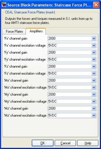
'Fx' channel gain (tunable online)
Select from the drop-down menu the 'Fx' channel gain (i.e., 1000, 2000, or 4000) set in the force plate MSA-6 amplifier by the jumper configuration for the 'Fx' channel gain. Referring to the MSA-6 strain gage amplifier manual, this is configured by jumper JP7.
'Fx' channel excitation voltage (tunable online)
Select from the drop-down menu the 'Fx' channel excitation voltage value (i.e., 2.5VDC, 5VDC, or 10VDC) set in the force plate MSA-6 amplifier by the jumper configuration for the 'Fx' channel excitation voltage. Referring to the MSA-6 strain gage amplifier manual, this is configured by jumper JP1.
'Fy' channel gain (tunable online)
Select from the drop-down menu the 'Fy' channel gain (i.e., 1000, 2000, or 4000) set in the MSA-6 amplifier by the jumper configuration for the 'Fy' channel gain. Referring to the MSA-6 strain gage amplifier manual, this is configured by jumper JP8.
'Fy' channel excitation voltage (tunable online)
Select from the drop-down menu the 'Fy' channel excitation voltage value (i.e., 2.5VDC, 5VDC, or 10VDC) set in the force plate MSA-6 amplifier by the jumper configuration for the 'Fy' channel excitation voltage. Referring to the MSA-6 strain gage amplifier manual, this is configured by jumper JP2.
'Fz' channel gain (tunable online)
Select from the drop-down menu the 'Fz' channel gain (i.e., 1000, 2000, or 4000) set in the force plate MSA-6 amplifier by the jumper configuration for the 'Fz' channel gain. Referring to the MSA-6 strain gage amplifier manual, this is configured by jumper JP9.
'Fz' channel excitation voltage (tunable online)
Select from the drop-down menu the 'Fy' channel excitation voltage value (i.e., 2.5VDC, 5VDC, or 10VDC) set in the force plate MSA-6 amplifier by the jumper configuration for the 'Fy' channel excitation voltage. Referring to the MSA-6 strain gage amplifier manual, this is configured by jumper JP3.
'Mx' channel gain (tunable online)
Select from the drop-down menu the 'Mx' channel gain (i.e., 1000, 2000, or 4000) set in the force plate MSA-6 amplifier by the jumper configuration for the 'Mx' channel gain. Referring to the MSA-6 strain gage amplifier manual, this is configured by jumper JP10.
'Mx' channel excitation voltage (tunable online)
Select from the drop-down menu the 'Mx' channel excitation voltage value (i.e., 2.5VDC, 5VDC, or 10VDC) set in the force plate MSA-6 amplifier by the jumper configuration for the 'Mx' channel excitation voltage. Referring to the MSA-6 strain gage amplifier manual, this is configured by jumper JP4.
'My' channel gain (tunable online)
Select from the drop-down menu the 'My' channel gain (i.e., 1000, 2000, or 4000) set in the force plate MSA-6 amplifier by the jumper configuration for the 'My' channel gain. Referring to the MSA-6 strain gage amplifier manual, this is configured by jumper JP11.
'My' channel excitation voltage (tunable online)
Select from the drop-down menu the 'My' channel excitation voltage value (i.e., 2.5VDC, 5VDC, or 10VDC) set in the force plate MSA-6 amplifier by the jumper configuration for the 'My' channel excitation voltage. Referring to the MSA-6 strain gage amplifier manual, this is configured by jumper JP5.
'Mz' channel gain (tunable online)
Select from the drop-down menu the 'Mz' channel gain (i.e., 1000, 2000, or 4000) set in the force plate MSA-6 amplifier by the jumper configuration for the 'Mz' channel gain. Referring to the MSA-6 strain gage amplifier manual, this is configured by jumper JP12.
'Mz' channel excitation voltage (tunable online)
Select from the drop-down menu the 'Mz' channel excitation voltage value (i.e., 2.5VDC, 5VDC, or 10VDC) set in the force plate MSA-6 amplifier by the jumper configuration for the 'Mz' channel excitation voltage. Referring to the MSA-6 strain gage amplifier manual, this is configured by jumper JP6.
Targets
|
Target Name |
Compatible* |
Model Referencing |
Comments |
|---|---|---|---|
|
Yes |
Yes |
||
|
Yes |
Yes |
||
|
Yes |
Yes |
||
|
Yes |
Yes |
||
|
Yes |
Yes |
||
|
Yes |
Yes |
||
|
Yes |
Yes |
||
|
Yes |
Yes |
||
|
Yes |
Yes |
||
|
Yes |
Yes |
||
|
Yes |
Yes |
||
|
Yes |
Yes |
||
|
Yes |
Yes |
||
|
Yes |
Yes |
Last fully supported in QUARC 2018. |
|
|
Rapid Simulation (RSIM) Target |
Yes |
Yes |
|
|
S-Function Target |
No |
N/A |
Old technology. Use model referencing instead. |
|
Normal simulation |
Yes |
Yes |
Copyright ©2026 Quanser Inc. This page was generated 2026-05-13. Submit feedback to Quanser about this page.
Link to this page.