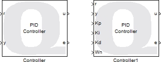

Controller
This block implements three commonly used controllers.
Library
QUARC Targets/Continuous MATLAB Command Line Click to copy the following command line to the clipboard. Then paste it in the MATLAB Command Window: qc_open_library('quarc_library/Continuous')
Description

The Controller block provides three different commonly used controllers:
Proportional-Integral-Derivative (PID)

This controller uses a proportional, integral and derivative term on the error to produce a control signal.
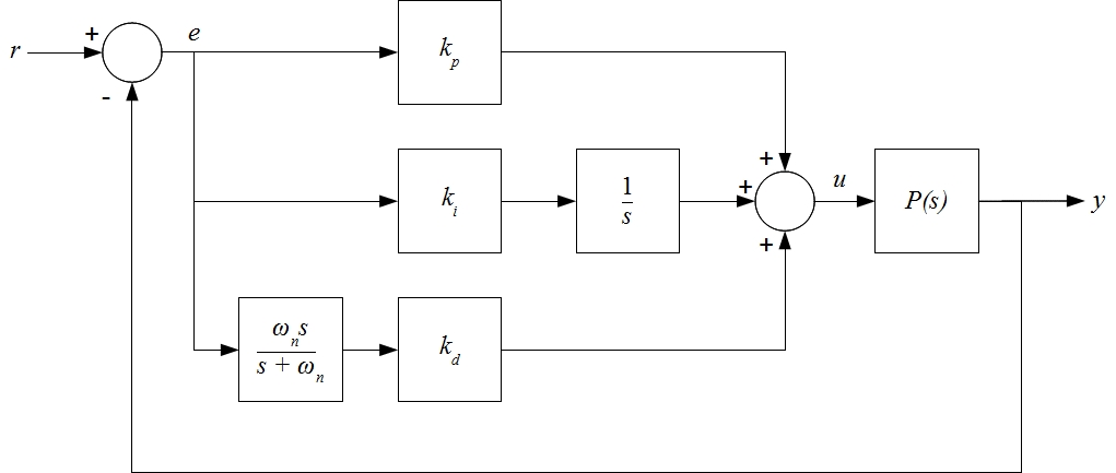
The PID control loop is depicted below and has the following structure: u = kp (r-y) + ki (r-y)/s + kd s (r-y). The direct derivative is not taken to minimize the noise in the control output. Instead, the first-order high-pass filter ωn s/(s+ωn) is used to compute the velocity of the error, where ωn is the cut-off frequency.

Proportional-Integral-Velocity (PIV)

This controller is like the PID controller except that the derivative term acts directly on the measured velocity rather than the error signal.
The PIV control loop is depicted below and has the following structure: u = kp (r-y) + ki (r-y)/s - kv s y. The direct derivative is not taken to minimize the noise in the control output. Instead, the first-order high-pass filter ωn s/(s+ωn) is used to compute the velocity of the error, where ωn is the cut off frequency. Unlike the PID control, PIV feeds back only the measured velocity (i.e. not the velocity of the error), which can lead to less overshoot in the closed-loop response.

PD with Acceleration Feedforward (PD with FF)

This controller measures the acceleration of the reference point, and feeds the signal to the PD controller to track the reference point.
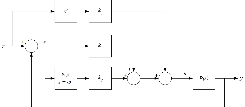
The PD+FF control loop is depicted below and has the following structure: u = kp (r-y) + kd s (r-y) + ka s2 r. The direct derivative is not taken to minimize the noise in the control output. Instead, the first-order high-pass filter ωn s/(s+ωn) is used to compute the velocity of the error, where ωn is the cut off frequency. Using the acceleration of the reference signal can lead to improved response time. Note that the computed acceleration of the reference signal is not signalled - it is assumed that the reference signal is sufficiently smooth. Ideally a Sigmoid block would be used to generate the reference signal.

This block not only provides a variety of controllers for users to choose from for their applications, it also makes gain scheduling possible by providing external ports for the gain parameters (when External input port is set in Source of parameters.)
Limitations
 In some cases, such as trajectory following, the Proportional-Integral-Velocity (PIV) controller is
not as stable as the rest of the controllers in terms of performance, because this controller assumes that
the reference point is stationary.
Input Ports
r
Reference point.
y
Current position of the system.
Kp
Proportional gain. This gain is multiplied by the error between the reference point and current position and added to the final output. This port only appears when Source of parameters is set to External input port.
Ki
Integral gain. This gain is multiplied by the integral of the error between the reference point and current position, and added to the final output. This port appears when the Controller Type is set to Proportional-Integral-Velocity (PIV) or Proportional-Integral-Differential (PID), and Source of parameters is set to External input port.
Kd
Derivative gain. This gain is multiplied by the derivative of the error between the reference point and current position and added to the final output. This port appears when the Controller Type is set to Proportional-Integral-Differential (PID) or PD with Acceleration Feedforward (PD with FF), and Source of parameters is set to External input port.
Kv
Velocity gain. This gain is multiplied by the derivative of the input y and added to the final output. This port appears when the Controller Type is set to Proportional-Integral-Velocity (PIV) and Source of parameters is set to External input port.
Ka
Acceleration feed-forward gain. This gain is multiplied by the acceleration of the reference point and added to the final output. This port appears when the Controller Type is set to PD with Acceleration Feedforward (PD with FF) and Source of parameters is set to External input port.
Wn
Cut-off frequency (in rad/s) for internal second-order low-pass filters. This port only appears when Source of parameters is set to External input port.
Output Ports
u
Controller output signal.
e
Error. Deviation of the current position from the reference point.
Data Type Support
The block inputs and outputs are of type double.
Parameters and Dialog Box

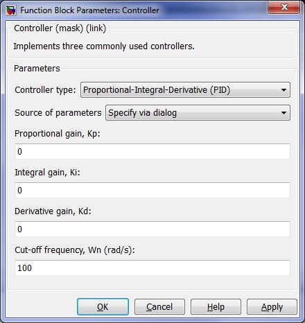
Controller type
Select the desired controller. The options are Proportional-Integral-Derivative (PID), Proportional-Integral-Velocity (PIV), and PD with Acceleration Feedforward (PD with FF).
Source of parameters
Specifies the source of parameters of the selected controller. The options are Specify via dialog and External input port.
Kp (tunable online)
Proportional gain. This gain is multiplied by the error between the reference point and current position and added to the final output. This parameter is only enabled when Source of parameters is set to Specify via dialog.
Ki (tunable online)
Integral gain. This gain is multiplied by the integral of the error between the reference point and current position, and added to the final output. This parameter appears when the Controller Type is set to Proportional-Integral-Differential (PID) or Proportional-Integral-Velocity (PIV), and is enabled when Source of parameters is set to Specify via dialog.
Kd (tunable online)
Derivative gain. This gain is multiplied by the derivative of the error between the reference point and current position and added to the final output. This parameter appears when the Controller Type is set to Proportional-Integral-Differential (PID) or PD with Acceleration Feedforward (PD with FF), and is enabled when Source of parameters is set to Specify via dialog.
Kv (tunable online)
Velocity gain. This gain is multiplied by the velocity of the system and added to the final output. This parameter appears when the Controller Type is set to Proportional-Integral-Velocity (PIV) and is enabled when Source of parameters is set to Specify via dialog.
Ka (tunable online)
Acceleration feed-forward gain. This gain is multiplied by the acceleration of the reference point and added to the final output. This parameter appears when the Controller Type is set to PD with Acceleration Feedforward (PD with FF) and is enabled when Source of parameters is set to Specify via dialog.
Wn (tunable online)
Cut-off frequency (in rad/s) for internal second-order low-pass filters. This parameter is only enabled when Source of parameters is set to Specify via dialog.
Targets
|
Target Name |
Compatible* |
Model Referencing |
Comments |
|---|---|---|---|
|
Yes |
Yes |
||
|
Yes |
Yes |
||
|
Yes |
Yes |
||
|
Yes |
Yes |
||
|
Yes |
Yes |
||
|
Yes |
Yes |
||
|
Yes |
Yes |
||
|
Yes |
Yes |
||
|
Yes |
Yes |
||
|
Yes |
Yes |
||
|
Yes |
Yes |
||
|
Yes |
Yes |
||
|
Yes |
Yes |
||
|
Yes |
Yes |
Last fully supported in QUARC 2018. |
|
|
Rapid Simulation (RSIM) Target |
Yes |
Yes |
|
|
S-Function Target |
No |
N/A |
Old technology. Use model referencing instead. |
|
Normal simulation |
Yes |
Yes |

Copyright ©2025 Quanser Inc. This page was generated 2025-11-01. Submit feedback to Quanser about this page.
Link to this page.