
Delcom Visual Indicator
 Controls a Delcom Visual Indicator, such as an LED beacon or traffic light.
Library
quarc_library/Devices/Third-Party/Delcom/Visual Indicators MATLAB Command Line Click to copy the following command line to the clipboard. Then paste it in the MATLAB Command Window: qc_open_library('quarc_library/Devices/Third-Party/Delcom/Visual Indicators')
Description
The Delcom Visual Indicator block is used to drive a Delcom Visual Indicator, such a multi-colour LED beacon or traffic light. It supports the optional buzzer and internal switch configurations as well. Features such as LED flashing and intensity may be controlled. For multi-colour indicators, the intensity and flashing of each LED may be driven independently for maximum flexibility. It is also possible to synchronize the flashing of the LEDs at any time.
Limitations
Current Limits
 Turning on all the LEDs at the same time at full power is not recommended, particularly with the red-green-blue combination.
With the 2 meter cable, all colours may be run at about 80% intensity at the same time if the USB port supports 500 mA per device.
With the 5 meter cable, the current limits are lower and no more than two of three LEDs should be on at the same time.
If the current limit is exceeded then the device will automatically turn off and the Delcom Visual Indicator block will return an error that the
device is not connected the next time it attempts to communicate with the device.
Turning on all the LEDs at the same time at full power is not recommended, particularly with the red-green-blue combination.
With the 2 meter cable, all colours may be run at about 80% intensity at the same time if the USB port supports 500 mA per device.
With the 5 meter cable, the current limits are lower and no more than two of three LEDs should be on at the same time.
If the current limit is exceeded then the device will automatically turn off and the Delcom Visual Indicator block will return an error that the
device is not connected the next time it attempts to communicate with the device.
Typical current consumptions are shown in the table below:
|
Colour/Power |
5% |
25% |
50% |
75% |
100% |
|---|---|---|---|---|---|
|
Red |
2 mA |
19 mA |
51 mA |
84 mA |
134 mA |
|
Yellow |
2 mA |
19 mA |
51 mA |
84 mA |
134 mA |
|
Blue |
2 mA |
29 mA |
81 mA |
130 mA |
200 mA |
|
Green |
3 mA |
34 mA |
95 mA |
150 mA |
225 mA |
Important Notes
Flash times
 The resolution of the flash on and off times, as well as the flash phase delays, is determined at model start
in order to provide the best accuracy possible for the requested times. However, if the optional sync
port is being used, this computed resolution may limit the maximum phase delay achievable at runtime more than desired.
Hence, in this circumstance, it is best to configure the initial phase delay values to the largest values that will
be used in order to ensure that phase delay values tuned at runtime are supported.
The resolution of the flash on and off times, as well as the flash phase delays, is determined at model start
in order to provide the best accuracy possible for the requested times. However, if the optional sync
port is being used, this computed resolution may limit the maximum phase delay achievable at runtime more than desired.
Hence, in this circumstance, it is best to configure the initial phase delay values to the largest values that will
be used in order to ensure that phase delay values tuned at runtime are supported.
Input Ports
The ports of the Delcom Visual Indicator block vary depending on the options selected.
green
The intensity of the green LED as a fraction between -1.0 and 1.0. If the intensity is negative then the LED will flash according to the Flash on time, Flash off time and Flash phase delay parameters. If the intensity is zero then the LED will be turned off. If the intensity is positive then the LED will be on steadily.
red
The intensity of the red LED as a fraction between -1.0 and 1.0. If the intensity is negative then the LED will flash according to the Flash on time, Flash off time and Flash phase delay parameters. If the intensity is zero then the LED will be turned off. If the intensity is positive then the LED will be on steadily.
blue
The intensity of the blue LED as a fraction between -1.0 and 1.0. If the intensity is negative then the LED will flash according to the Flash on time, Flash off time and Flash phase delay parameters. If the intensity is zero then the LED will be turned off. If the intensity is positive then the LED will be on steadily.
yellow
The intensity of the yellow LED as a fraction between -1.0 and 1.0. If the intensity is negative then the LED will flash according to the Flash on time, Flash off time and Flash phase delay parameters. If the intensity is zero then the LED will be turned off. If the intensity is positive then the LED will be on steadily.
bfreq
The audible frequency of the buzzer in Hertz. If this value is zero then the buzzer is turned off. The buzzer is triggered whenever this input changes. It will then sound with the given frequency and turn on and off for the Buzzer on time and Buzzer off time respectively for the number of times indicated by the Buzzer repeat count parameter.
bstart
The buzzer is triggered on a rising edge at this input. A rising edge is defined as the input rising from a negative or zero value to a positive value. If this input is positive at model start then the buzzer will be triggered immediately. When triggered, the buzzer will then sound with the frequency specified in the Buzzer frequency parameter and turn on and off for the Buzzer on time and Buzzer off time respectively. It will repeat this on/off cycle for the number of times indicated by the Buzzer repeat count parameter.
bstop
The buzzer is stopped on a rising edge at this input. A rising edge is defined as the input rising from a negative or zero value to a positive value. If this input is positive at model start then it will nullify the effect of the bstart input being positive at model start. This input is useful when the Buzzer repeat count is zero, indicating a continuous sound.
sync
A rising edge on this input causes the LED flashing to be synchronized such that each LED begins flashing (if flashing is enabled by the corresponding intensity input) with the relative phase delays configured by the Flash phase delay parameter. A rising edge is defined as the input rising from a negative or zero value to a positive value. If this input is positive at model start then the LED flashing will be synchronized in the first sampling instant. However, there is no benefit in doing so because the LEDs are always synchronized at model start.
Output Ports
switch
The number of times a rising or falling edge has occurred on the internal switch since the last time this block was invoked. Whether rising or falling edges are detected is selected by the Switch parameter. This output is only present when an option other than has been selected.
Parameters and Dialog Box
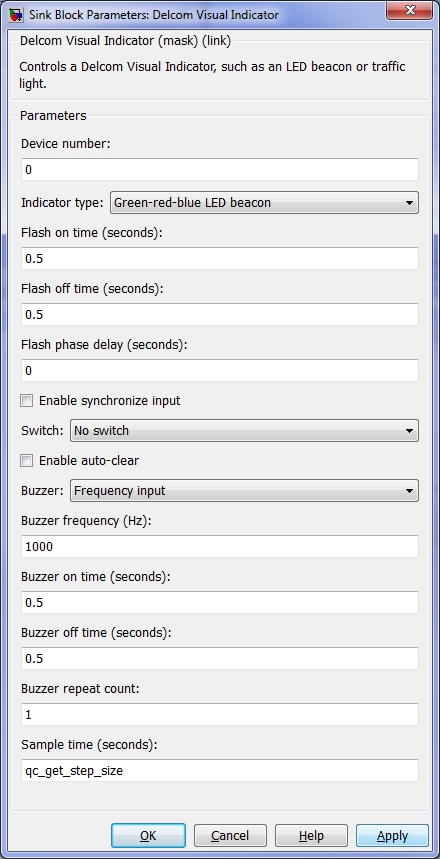
Device number
The number of the visual indicator. This parameter is used to distinguish between multiple indicators.
Indicator type
The type of visual indicator being used. This parameter is used determine the number of colours supported by the device and the names of the colours. The input port labels will change accordingly.
Flash on time (tunable offline)
The duration for which an LED will be on during flashing, in seconds. This parameter may be a scalar or vector. If it is a vector, then each element corresponds to a different LED colour. The elements are ordered the same as the input ports.
Flash off time (tunable offline)
The duration for which an LED will be off during flashing, in seconds. This parameter may be a scalar or vector. If it is a vector, then each element corresponds to a different LED colour. The elements are ordered the same as the input ports.
Flash phase delay (tunable offline)
The initial phase delay for flashing, in seconds. The phase delay may be used to offset the flashing between individual LEDs. This parameter may be a scalar or vector. If it is a vector, then each element corresponds to a different LED colour. The elements are ordered the same as the input ports. The phase delays are programmed at model start. If the Enable synchronize input parameter is checked then they are also programmed each time a rising edge is seen on the sync input. In that case, the phase delays are tunable during runtime, but only take effect on the next rising edge of the sync input.
Enable synchronize input
Check this option to enable the sync port for synchronizing LED flashing. Note that the LED flashing is synchronized at model start, so this option is only useful in general if the flashing period of each LED is different and they need to be resynchronized after model start.
Switch
The Delcom Visual Indicators come with an optional internal switch. Use this option to read the switch. The Delcom Visual Indicator block can count the number of times a rising or falling edge has occurred on the switch since the last time the block was invoked, even between sampling instants. This count is output from the switch output when a switch is selected.
Enable auto-clear (tunable offline)
Check this option to enable the internal switch to clear the LEDs whenever it is pressed.
Buzzer frequency (tunable online)
The audible frequency of the buzzer in Hz.
Buzzer on time (tunable online)
The duration for which the buzzer will be on when triggered, in seconds. This value is only used when the buzzer is triggered.
Buzzer off time (tunable online)
The duration for which the buzzer will be off when triggered, in seconds. This value is only used when the buzzer is triggered.
Buzzer repeat count (tunable offline)
The buzzer will go on and off for the number of times specified by this parameter. If this parameter is set to zero then the buzzer will continue its cycle indefinitely or until a rising edge at the bstop input stops the buzzer. This value is only used when the buzzer is triggered.
Sample time
The sample time of the block. A sample time of 0 indicates that the block will be treated as a continuous time block. A positive sample time indicates that the block is a discrete time block with the given sample time.
A sample time of -1 indicates that the block inherits its sample time from the input. The block inherits the sample time by default.
To set the sample time to the fundamental sampling time of the model, use the qc_get_step_size function, which is a QUARC function that returns the fundamental sampling time of the model. The fundamental sampling time of the model is the sampling time entered in the Fixed step size field of the Solver pane of the Configuration parameters.
Targets
|
Target Name |
Compatible* |
Model Referencing |
Comments |
|---|---|---|---|
|
Yes |
Yes |
||
|
Yes |
Yes |
||
|
No |
No |
||
|
No |
No |
||
|
No |
No |
||
|
No |
No |
||
|
No |
No |
||
|
No |
No |
||
|
No |
No |
||
|
No |
No |
||
|
No |
No |
||
|
No |
No |
||
|
No |
No |
||
|
No |
No |
Last fully supported in QUARC 2018. |
|
|
Rapid Simulation (RSIM) Target |
No |
No |
|
|
S-Function Target |
No |
N/A |
Old technology. Use model referencing instead. |
|
Normal simulation |
No |
No |
Copyright ©2026 Quanser Inc. This page was generated 2026-05-13. Submit feedback to Quanser about this page.
Link to this page.