
Gumstix Robostix
| Support for the Gumstix Robostix is deprecated because the product lines using the Gumstix Verdex have been replaced with hardware based on the Gumstix DuoVero. Refer to the QUARC Linux DuoVero Target for details. |
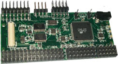
The Gumstix's Robostix is a board built and sold by Gumstix, Inc. (www.gumstix.com). The Robostix is based around the Atmel ATMega128 AVR processor. Even though the Gumstix Robostix can run code as a standalone microcontroller, it can only be used with QUARC when connected to a Gumstix Verdex board. In this configuration, communication between the Robostix and the Verdex (which is where QUARC actually runs) is done using the Inter-Integrated Circuit (I2C) bus. More precisely, the gumstix configured as the I2C master sends commands for performing I/O to the Robostix which is set as the I2C slave. Please see the Gumstix's website (www.gumstix.com)for more information about the Robostix. The following characteristics are of particular interest when using the Robostix with QUARC:
The features of the Gumstix Robostix are:
To select the Robostix, select the QUARC driver robostix from the drop-down list on the Main tab of the HIL Initialize block.
Please note that only one Robostix card can be connected to a Verdex board and is supported in the system. The QUARC controller runs on the Verdex board and communicates with the Robostix firmware using I2C.
| Note that the Linux Verdex target must be selected to use the Robostix board, as it is connected to the Verdex board. |
The QUARC driver name for this card is robostix.
Installation Requirements
 In order to use the Robostix HIL driver, the Robostix AVR and Gumstix will need to be setup. Refer
to Gumstix and Robotstix Setup for more details.
In order to use the Robostix HIL driver, the Robostix AVR and Gumstix will need to be setup. Refer
to Gumstix and Robotstix Setup for more details.
On the Verdex side, the robostix.ko kernel module should be loaded and the /dev/robostix device should be available. Also the
I2C kernel drivers (i.e., i2c_dev.ko, i2c_pxa.ko, and i2c_core.ko) should also be running to allow
communication between the Verdex and Robostix boards.
Clocks
The Robostix driver currently supports two (2) clocks, which are both only used to generate the PWM output(s). Clock 0 corresponds to Robostix Timer 1. Clock 1 corresponds to Robostix Timer 3.
The Robostix driver does not currently support any hardware timebase. Only the PWM output clock mode is supported at present. Hence, set the
Clock mode field to 1 to select the PWM output mode.
Analog Inputs
The Robostix driver supports 8 analog inputs, corresponding to the Robostix 10-bit Analog-to-Digital (A/D) converter located on port F. Hence, analog input channel numbers range from 0 to 7. Only positive voltages are measured, ranging from 0V (i.e., ground) to +5V.
Since the range of the analog inputs is fixed at 0-5V, there is no need to configure the analog input ranges.
Analog Outputs
The Gumstix Robostix card does not support analog outputs.
Digital Inputs
The Robostix driver supports 16 digital lines, which can be configured by the user either as digital input(s) or digital output(s). Digital channels 0 to 7 correspond to Robostix Port A (from port A.0 to A.7, respectively) and digital channels 8 to 15 correspond to Robostix Port C (from port C.0 to port C.7, respectively). A digital I/O line cannot be used as an input and output at the same time.
Since the 16 digital I/O lines may be individually programmed as inputs or outputs on the Robostix, all of those 16 channels which will be
used for digital inputs should be configured on the HIL Initialize block's
Digital Inputs tab. Set the Digital input channels field to all the digital I/O channels that will be
used as digital inputs on the board for the current diagram. For example, enter 9:12 to designate channels 9 through 12 as digital
inputs. Specify [8, 11, 14] to indicate that channels 8, 11, and 14 are to be configured as digital inputs.
Digital Outputs
The Robostix driver supports 16 digital lines, which can be configured by the user either as digital input(s) or digital output(s). Digital channels 0 to 7 correspond to Robostix Port A (from port A.0 to A.7, respectively) and digital channels 8 to 15 correspond to Robostix Port C (from port C.0 to port C.7, respectively). A digital I/O line cannot be used as an input and output at the same time.
Since the 16 digital I/O lines may be individually programmed as inputs or outputs on the Robostix, all of those 16 channels which will be
used for digital outputs should be configured on the HIL Initialize block's
Digital Outputs tab. Set the Digital output channels field to all the digital I/O channels that will be
used as digital outputs on the board for the current diagram. For example, enter 9:12 to designate channels 9 through 12 as digital
outputs. Specify [8, 11, 14] to indicate that channels 8, 11, and 14 are to be configured as digital outputs.
To set the digital output values when the model is loaded or unloaded, set the Initial digital outputs and Final digital outputs to the desired values respectively. If the vectors specified in these fields are shorter than the channel vector, the value of the last element in the vector will be used for the rest of the channels. Hence, a scalar value will apply to all channels specified in the Digital output channels field.
Encoder Inputs
The Gumstix Robostix card does not support encoder inputs.
PWM Outputs
The Robostix driver supports six (6) PWM output channels, using two of the Robostix hardware clocks, i.e., Robostix Timer 1 and Timer 3. See the section on Clocks above. Hence, PWM output channels range from 0 to 5. PWM output channels 0 to 2 correspond to Robostix PWM 1A, 1B, and 1C (from Clock 0 , a.k.a., Robostix Timer 1), respectively. PWM output channels 3 to 5 correspond to Robostix PWM 3A, 3B, and 3C (from Clock 1 , a.k.a., Robostix Timer 3), respectively.
In order to configure the PWM mode or frequency, or to set the value of the PWM outputs when the model is loaded or unloaded, the PWM outputs
must be configured on the HIL Initialize block's PWM Outputs
tab. Set the PWM output channels field to all the PWM output channels that will be used on the board for the current
diagram. For example, enter 0:1 to indicate channels 0 and 1, which correspond to the Robostix PWM 1A and PWM 1B channels. Specify 1
to indicate channel 1 alone.
The PWM output frequency (a.k.a., pulse rate) is suitable to drive R/C servos. Specifically, it is set to 50 Hz, which is equivalent to a
PWM output period of 20 ms. Hence, set the PWM output mode field to 0 the duty cycle output mode. The Robostix
driver does not currently support the frequency and period PWM output modes. Then set the
"Frequencies in Hz or duty cycle" field to 50 Hz, the desired frequency. The Robostix driver
supports duty cycles ranging from 2.5% (i.e., a 0.5-ms pulse width) to 12.5% (i.e., a 2.5-ms pulse width), which is suitable for typical R/C
servo applications. Finally, set the Initial PWM outputs and Final PWM outputs fields to the desired
initial and final duty cycles, respectively. For example, enter 0.075 to indicate a 7.5 % duty cycle. A 7.5% duty cycle (i.e., a
1.5-ms pulse width) typically corresponds to the neutral position for R/C servos. If the vectors specified in these fields are shorter than
the channel vector, the value of the last element in the vector will be used for the rest of the channels. Hence, a scalar value will apply
to all channels specified in the PWM output channels field.
Other Inputs
The Gumstix Robostix card does not support other inputs.
Other Outputs
The Gumstix Robostix card does not support other outputs.
Interrupts
The Gumstix Robostix card, or its driver, does not support any interrupt sources.
Watchdog
The Gumstix Robostix card does not support a watchdog timer.
Board-Specific Options
The Gumstix Robostix card does not support any board-specific options.
Properties
The Gumstix Robostix card does not support any properties.
Targets
|
Target |
Supported |
Comments |
|---|---|---|
|
No |
Not supported. |
|
|
No |
Not supported. |
|
|
No |
Not supported. |
|
|
No |
Not supported. |
|
|
No |
Not supported. |
|
|
No |
Not supported. |
|
|
No |
Not supported. |
|
|
No |
Not supported. |
|
|
No |
Not supported. |
|
|
No |
Not supported. |
|
|
No |
Not supported. |
|
|
No |
Not supported. |
|
|
No |
Not supported. |
|
|
Yes |
Fully supported. |
|
|
No |
Not supported. |
|
|
Rapid Simulation (RSIM) Target |
Yes |
Supported with no communication to the hardware. |
|
Normal simulation |
Yes |
Supported with no communication to the hardware. |
See Also
Copyright ©2026 Quanser Inc. This page was generated 2026-05-13. Submit feedback to Quanser about this page.
Link to this page.

