
HIL Initialize
Initializes an HIL board and associates a name with the board.
Library
QUARC Targets/Data Acquisition/Generic/Configuration MATLAB Command Line Click to copy the following command line to the clipboard. Then paste it in the MATLAB Command Window: qc_open_library('quarc_library/Data Acquisition/Generic/Configuration')
Description

The HIL Initialize block associates a name with a particular HIL board. The name specified in the Board name parameter will be the name of the board. This name will appear in the list of boards for every other HIL block. Using a separate block to configure the HIL board makes it trivial to change the HIL hardware being used.
| As of MATLAB R2014b, the label on the first edit field of each tab may be clipped due to internal inconsistencies in newer versions of MATLAB. Resizing the HIL Initialize dialog will cause the missing text to be shown on the active tab. A workaround is currently being implemented. |
Input Ports
This block has no input ports.
Output Ports
This block has no output ports.
Parameters and Dialog Box
Common Buttons
The dialog box for the HIL Initialize block contains the usual , and buttons for agreeing to the changes, cancelling the changes and getting help respectively. It also contains an additional button called . The button is used to reset the values of all the fields to default values for the selected board type. These values are the same ones as those assigned the first time a particular board type is selected. The values are specific to the board type and only affect the parameter values for that board type. The values entered for other board types will not be affected.
Goto HIL blocks using this board
Opens a dialog that lists all the HIL blocks in the model which are currently using the same board selected in the Board name parameter. The dialog may be used to go to another HIL block in the model just by double-clicking on the name of the block in the dialog box.
Individual Panes
Main Pane
The Main pane of the dialog appears as follows:
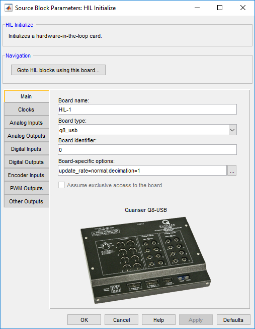
Board name
The name to assign to the board. This name will show up in the list of boards for the other HIL blocks. It is this name that associates the other HIL blocks with the data acquisition card selected by this block.
Board type
The type of HIL board being configured. For example, for the Q8 board the board type is q8.
The HIL Initialize block preserves the parameter settings for each board type selected. Hence, each time a board type is selected from the list, the parameter values in all the other fields of the dialog box will change to reflect the settings last entered for that board type. When a board type is selected for the first time, the other parameter values are initialized to default values specific to that board type. Since different boards often have a different number of I/O channels and different features, maintaining the parameter values on a per-board basis makes it possible to experiment with different boards without losing the parameter values specific to each board.
Board identifier
The identifier of the board. This parameter is used to differentiate between boards when there is more than one board of the given type in the computer. Typically, this parameter is 0, indicating the first board of the given type. Subsequent boards are numbered sequentially. Hence, the second board in the system is board 1. There are other ways that this parameter can be specified. Some board types support the use of a device name as the board identifier, such as "Dev1", others support the use of a "x.y" notation. Refer to the individual board type's docuementation for more details.
Board-specific options
Options that are specific to this board type. This field is generally a string of the form:
name=value[,name=value...]
where the name is the name of an option and the value is the value to assign to that option. No spaces should appear between name/value pairs. For example,
EncDir=1,Pin0=pwm
Board-specific options are documented in the help associated with the board type. Select a board type from the list for board-specific details: .
Clocks Pane
The Clocks pane of the dialog appears as follows:
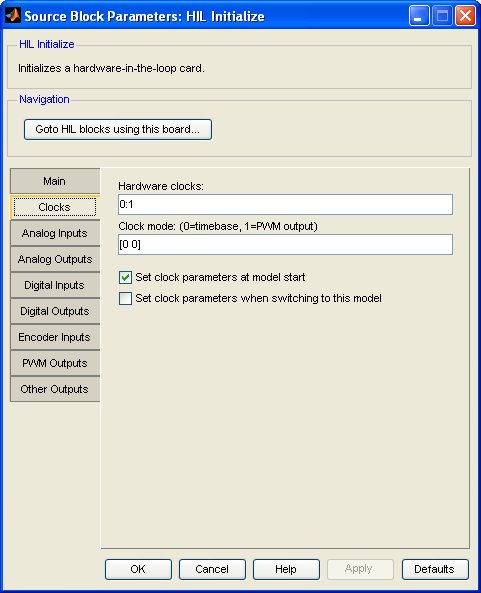
Hardware clocks
The hardware clocks to configure. This parameter may be a vector or scalar. Enter 0 for HARDWARE_CLOCK_0, 1 for HARDWARE_CLOCK_1, etc. The number of clocks available depends on the board selected. Refer to Clocks for more information.
Select a board type from the list for board-specific details: .
Clock mode
The mode to use for each hardware clock. This parameter may be a vector or scalar. If this parameter has fewer elements than the Hardware clocks parameter then the value of the last element will be used for the rest of the hardware clocks.
Mode 0 is timebase mode. In timebase mode the hardware clock is configured as a hardware timebase. As a hardware timebase it may be used for buffered I/O, timebases and stream I/O as the timebase.
Mode 1 is PWM output mode. In PWM output mode the hardware clock is configured as a PWM output. This mode is not supported by all cards. If a clock is configured in PWM output mode then it may be used with the HIL PWM blocks as an output but may not be used as a hardware timebase.
Mode 2 is encoder input mode. In encoder input mode the hardware clock is configured as an encoder input. This mode is not supported by all cards. If a clock is configured in encoder input mode then it may be used with the HIL Encoder blocks as an input but may not be used as a hardware timebase.
Initial clock frequencies
This parameter is used to pre-program a hardware clock with a particular frequency. Each element in this vector parameter corresponds to the respective clock in the Hardware clocks field. Unlike most parameters, if there are fewer elements than the Hardware clocks field then only the initial clock frequencies specified are set. The rest of the clocks are not programmed with an initial clock frequency. This field is ignored if neither the Set initial clock frequencies at model start nor Set initial clock frequencies when switching to this model option are checked.
Setting the initial clock frequency is not required to use the clock as a hardware timebase for the HIL Timebase blocks or hil_task functions. Its primary purpose is for programming clocks that will not be used as a hardware timebase but instead may be used for interrupt generation, or other purposes.
| In fact, if the clock is used as a hardware timebase then the initial clock frequency that is set will be overridden. It is best not to initialize a clock being used as a hardware timebase by leaving the Initial clock frequencies parameter as an empty matrix, or setting the element corresponding to the hardware timebase clock to zero. |
For example, the Quanser QPID and Quanser QPIDe cards can generate interrupts when one of the first four analog inputs surpasses a specified threshold. However, to ensure that the card is performing analog-to-digital conversions in order to check the threshold, its 24-bit COUNTER general purpose clock must be configured to trigger A/D conversions, and the frequency of the clock must be set. The Initial clock frequencies parameter allows the frequency of this clock to be set, without using it as a hardware timebase to time a model or task.
Set clock parameters at model start
Check this option to configure the clock modes for the selected hardware clocks when the model is started. If this option is not checked then the clock modes will not be configured at model start. In this case, the existing clock modes will be used.
Set clock parameters when switching to this model
Check this option to configure the clock modes for the selected hardware clocks when switching to this model using the dynamic reconfiguration capabilities of QUARC. If this option is not checked then the clock modes will not be configured when switching to this model dynamically. In this case, the existing clock modes will be used. Refer to Dynamic Reconfiguration for more information.
Set initial clock frequencies at model start
Check this option to initialize the clock frequencies for the selected hardware clocks when the model is started. If this option is not checked then the clock frequencies will not be configured at model start.
Set initial clock frequencies when switching to this model
Check this option to initialize the clock frequencies for the selected hardware clocks when switching to this model using the dynamic reconfiguration capabilities of QUARC. If this option is not checked then the clock frequencies will not be configured when switching to this model dynamically. Refer to Dynamic Reconfiguration for more information on dynamic reconfiguration.
Analog Inputs Pane
The Analog Inputs pane of the dialog appears as follows:
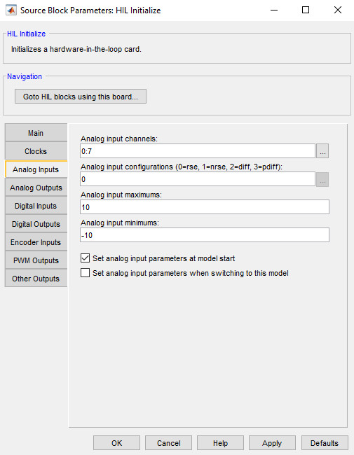
Analog input channels
The analog input channels to configure. This parameter may be a vector or scalar. The number of analog inputs available depends on the board selected.
Select a board type from the list for board-specific details: .
Analog input configurations
Many cards support a programmable analog input configuration. This parameter allows the analog input configuration to be configured. This parameter may be a vector or scalar. If this parameter has fewer elements than the Analog input channels parameter then the value of the last element will be used for the rest of the analog input channels. The specified configuration must be supported by the card selected on the Main tab.
In the rse (referenced single-ended) configuration (0), the analog input measurement is made with respect to the ground, that is connected to the card's ground.
In the nrse (non-referenced single-ended) configuration (1), the analog input measurement is made with respect to a common ground, that may/may not be connected to the card's ground.
In the diff (differential) configuration (2), the analog input measurement is made with between the positive and negative inputs. The negative input can be a floating ground that is not tied to any fixed reference.
In the pdiff (pseudo-differential) configuration (3), it is similar to the differentail configuration, but the negative input is tied to the system ground through a relatively small impedance.
Analog input maximums
Many cards support a programmable analog input range. This parameter allows the maximum value in the analog input range to be configured. This parameter may be a vector or scalar. If this parameter has fewer elements than the Analog input channels parameter then the value of the last element will be used for the rest of the analog input channels. For example, for a 10V bipolar input range set the analog input maximum to 10 and the analog input minimum to -10. For a 10V unipolar input range set the analog input maximum to 10 and the analog input minimum to 0. The specified range must be supported by the card selected on the Main tab.
Analog input minimums
Many cards support a programmable analog input range. This parameter allows the minimum value in the analog input range to be configured. This parameter may be a vector or scalar. If this parameter has fewer elements than the Analog input channels parameter then the value of the last element will be used for the rest of the analog input channels. For example, for a 10V bipolar input range set the analog input maximum to 10 and the analog input minimum to -10. For a 10V unipolar input range set the analog input maximum to 10 and the analog input minimum to 0. The specified range must be supported by the card selected on the Main tab.
Set analog input parameters at model start
Check this option to configure the analog input ranges for the selected analog input channels when the model is started. If this option is not checked then the analog input ranges will not be configured at model start. In this case, either the existing ranges will be used.
Set analog input parameters when switching to this model
Check this option to configure the analog input ranges for the selected analog inputs when switching to this model using the dynamic reconfiguration capabilities of QUARC. If this option is not checked then the analog input ranges will not be configured when switching to this model dynamically. In this case, the existing ranges will be used. Refer to Dynamic Reconfiguration for more information.
Analog Outputs Pane
The Analog Outputs pane of the dialog appears as follows:
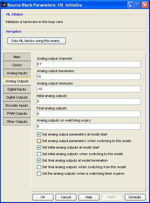
Analog output channels
The analog output channels to configure. This parameter may be a vector or scalar. The number of analog outputs available depends on the board selected.
Select a board type from the list for board-specific details: .
Analog output maximums
Some cards support a programmable analog output range. This parameter allows the maximum value in the analog output range to be configured. This parameter may be a vector or scalar. If this parameter has fewer elements than the Analog output channels parameter then the value of the last element will be used for the rest of the analog output channels. For example, for a 10V bipolar output range set the analog output maximum to 10 and the analog output minimum to -10. For a 10V unipolar output range set the analog output maximum to 10 and the analog output minimum to 0. The specified range must be supported by the card selected on the Main tab.
Analog output minimums
Some cards support a programmable analog output range. This parameter allows the minimum value in the analog output range to be configured. This parameter may be a vector or scalar. If this parameter has fewer elements than the Analog output channels parameter then the value of the last element will be used for the rest of the analog output channels. For example, for a 10V bipolar output range set the analog output maximum to 10 and the analog output minimum to -10. For a 10V unipolar output range set the analog output maximum to 10 and the analog output minimum to 0. The specified range must be supported by the card selected on the Main tab.
Initial analog outputs
The value(s) to output on the selected analog output channels when the model is started or when switching to this model dynamically. This parameter may be a vector or scalar. If this parameter has fewer elements than the Analog output channels parameter then the value of the last element will be used for the rest of the analog output channels. If neither the Set initial analog outputs at model start nor Set initial analog outputs when switching to this model parameters are checked then this option is ignored.
Final analog outputs
The value(s) to output on the selected analog output channels when the model is terminated or when switching from this model dynamically. This parameter may be a vector or scalar. If this parameter has fewer elements than the Analog output channels parameter then the value of the last element will be used for the rest of the analog output channels. If neither the Set final analog outputs at model termination nor Set final analog outputs when switching from this model parameters are checked then this option is ignored.
Analog outputs on watchdog expiry
The value(s) to output on the selected analog output channels if the watchdog timer expires. The watchdog timer is only used if a HIL Watchdog is present in the model. If this parameter has fewer elements than the Analog output channels parameter then the value of the last element will be used for the rest of the analog output channels. This parameter is ignored unless the Set the analog outputs when a watchdog timer expires option is checked.
Set analog output parameters at model start
Check this option to configure the analog output ranges for the selected analog output channels when the model is started. If this option is not checked then the analog output ranges will not be configured at model start. In this case, either the existing ranges will be used.
Set analog output parameters when switching to this model
Check this option to configure the analog output ranges for the selected analog outputs when switching to this model using the dynamic reconfiguration capabilities of QUARC. If this option is not checked then the analog output ranges will not be configured when switching to this model dynamically. In this case, either the existing ranges will be used. Refer to Dynamic Reconfiguration for more information.
Set initial analog outputs at model start
Check this option to write the Initial analog outputs values to the selected analog outputs when the model is started. If this option is not checked then the analog outputs will not be written at model start. In this case, the analog outputs will remain at their current values until the first time they are written by other HIL blocks in the diagram.
Set initial analog outputs when switching to this model
Check this option to write the Initial analog outputs values to the selected analog outputs when switching to this model using the dynamic reconfiguration capabilities of QUARC. If this option is not checked then the analog outputs will not be written when switching to this model dynamically. In this case, the analog outputs will remain at their current values until the first time they are written by other HIL blocks in the diagram. Refer to Dynamic Reconfiguration for more information.
Set final analog outputs at model termination
Check this option to write the Final analog outputs values to the selected analog outputs when the model is terminated. If this option is not checked then the analog outputs will not be written at model termination. In this case, the analog outputs will remain at their current values.
Set final analog outputs when switching from this model
Check this option to write the Final analog outputs values to the selected analog outputs when switching from this model using the dynamic reconfiguration capabilities of QUARC. If this option is not checked then the analog outputs will not be written when switching from this model dynamically. In this case, the analog outputs will remain at their current values. Refer to Dynamic Reconfiguration for more information.
Set the analog outputs when a watchdog timer expires
Check this option to write the Analog outputs on watchdog expiry values to the selected analog outputs when the watchdog timer expires. If this option is not checked then the analog outputs will not be written when the watchdog timer expires. In this case, the analog outputs will remain at their current values. The watchdog timer is only used if a HIL Watchdog is present in the model. Refer to the HIL Watchdog block for more information.
Digital Inputs Pane
The Digital Inputs pane of the dialog appears as follows:
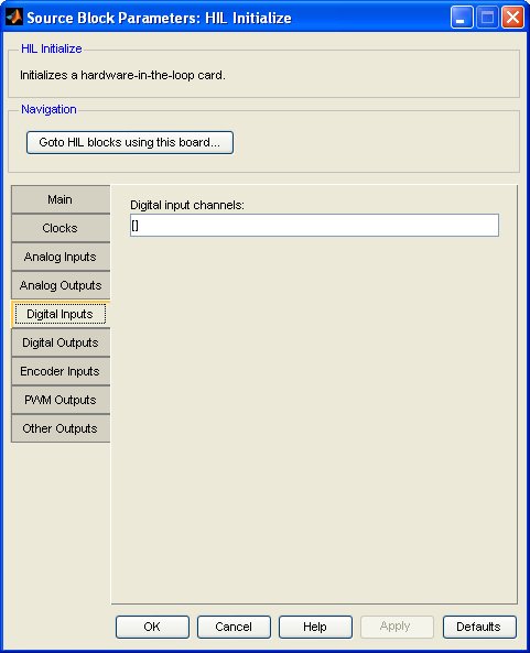
Digital input channels
The digital input channels to configure. This parameter may be a vector or scalar. The number of digital inputs available depends on the board selected. This option is important for boards which support programmable digital I/O because it is used to set the directions of the digital I/O lines. Channels which are listed in this parameter will be configured as digital inputs. If this parameter is empty then the HIL Initialize block will not attempt to configure any digital I/O lines as digital inputs. Channels listed on the Digital Outputs tab will be configured as digital outputs. Any digital I/O channels which are not included on either of these tabs will be left in their existing configuration.
Select a board type from the list for board-specific details: .
Digital Outputs Pane
The Digital Outputs pane of the dialog appears as follows:
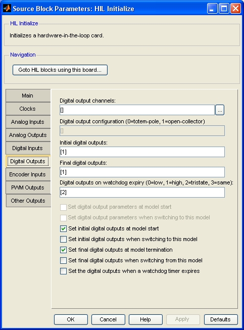
Digital output channels
The digital output channels to configure. This parameter may be a vector or scalar. The number of digital outputs available depends on the board selected. This option is important for boards which support programmable digital I/O because it is used to set the directions of the digital I/O lines. Channels which are listed in this parameter will be configured as digital outputs. If this parameter is empty then the HIL Initialize block will not attempt to configure any digital I/O lines as digital outputs. Channels listed on the Digital Inputs tab will be configured as digital inputs. Any digital I/O channels which are not included on either of these tabs will be left in their existing configuration.
Select a board type from the list for board-specific details: .
Initial digital outputs
The value(s) to output on the selected digital output channels when the model is started or when switching to this model dynamically. This parameter may be a vector or scalar. If this parameter has fewer elements than the Digital output channels parameter then the value of the last element will be used for the rest of the digital output channels. If neither the Set initial digital outputs at model start nor Set initial digital outputs when switching to this model parameters are checked then this option is ignored.
Final digital outputs
The value(s) to output on the selected digital output channels when the model is terminated or when switching from this model dynamically. This parameter may be a vector or scalar. If this parameter has fewer elements than the Digital output channels parameter then the value of the last element will be used for the rest of the digital output channels. If neither the Set final digital outputs at model termination nor Set final digital outputs when switching from this model parameters are checked then this option is ignored.
Digital outputs on watchdog expiry
The value(s) to output on the selected digital output channels if the watchdog timer expires. The watchdog timer is only used if a HIL Watchdog is present in the model. If this parameter has fewer elements than the Digital output channels parameter then the value of the last element will be used for the rest of the digital output channels. Valid values for each elements are 0, 1, 2 or 3. A value of 0 indicates that the digital output should go low on watchdog expiration, while a value of 1 indicates that the output should go high. A value of 2 indicates that the digital output should go tristate. In other words, it should act as an input if the watchdog expires. Finally, a value of 3 indicates that the digital output should not change when the watchdog expires. This parameter is ignored unless the Set the digital outputs when a watchdog timer expires option is checked.
Set initial digital outputs at model start
Check this option to write the Initial digital outputs values to the selected digital outputs when the model is started. If this option is not checked then the digital outputs will not be written at model start. In this case, the digital outputs will remain at their current values until the first time they are written by other HIL blocks in the diagram.
Set initial digital outputs when switching to this model
Check this option to write the Initial digital outputs values to the selected digital outputs when switching to this model using the dynamic reconfiguration capabilities of QUARC. If this option is not checked then the digital outputs will not be written when switching to this model dynamically. In this case, the digital outputs will remain at their current values until the first time they are written by other HIL blocks in the diagram. Refer to Dynamic Reconfiguration for more information.
Set final digital outputs at model termination
Check this option to write the Final digital outputs values to the selected digital outputs when the model is terminated. If this option is not checked then the digital outputs will not be written at model termination. In this case, the digital outputs will remain at their current values.
Set final digital outputs when switching from this model
Check this option to write the Final digital outputs values to the selected digital outputs when switching from this model using the dynamic reconfiguration capabilities of QUARC. If this option is not checked then the digital outputs will not be written when switching from this model dynamically. In this case, the digital outputs will remain at their current values. Refer to Dynamic Reconfiguration for more information.
Set the digital outputs when a watchdog timer expires
Check this option to write the Digital outputs on watchdog expiry values to the selected digital outputs when the watchdog timer expires. If this option is not checked then the digital outputs will not be written when the watchdog timer expires. In this case, the digital outputs will remain at their current values. The watchdog timer is only used if a HIL Watchdog is present in the model. Refer to the HIL Watchdog block for more information.
Encoder Inputs Pane
The Encoder Inputs pane of the dialog appears as follows:
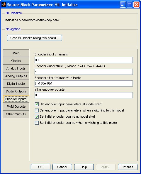
Encoder input channels
The encoder input channels to configure. This parameter may be a vector or scalar. The number of encoder inputs available depends on the board selected.
Select a board type from the list for board-specific details: .
Encoder quadrature
Many cards support different encoder quadrature modes. This parameter allows the quadrature of the encoder inputs to be configured. This parameter may be a vector or scalar. If this parameter has fewer elements than the Encoder input channels parameter then the value of the last element will be used for the rest of the encoder input channels. The specified quadrature modes must be supported by the card selected on the Main tab.
Quadrature mode 0 indicates no quadrature. In this case, the A and B channels of the encoder are typically treated as counter and direction inputs. The exact meaning of this mode depends on the card selected on the Main tab. For example, for the Quanser Q8 hardware-in-the-loop card the A channel becomes a count input and the B channel becomes a direction input.
Quadrature mode 1 indicates 1X quadrature mode. In this case, the A and B channels of the encoder are treated as standard encoder inputs but only one count is produced for each input pulse or "quadrature cycle".
Quadrature mode 2 indicates 2X quadrature mode. In this case, the A and B channels of the encoder are treated as standard encoder inputs and two counts are produced for each input pulse or "quadrature cycle".
Quadrature mode 4 indicates 4X quadrature mode. In this case, the A and B channels of the encoder are treated as standard encoder inputs and the full four counts are produced for each input pulse or "quadrature cycle".
Encoder filter frequency in Hertz
Many cards support a programmable encoder input filter frequency. This parameter allows the filter frequency to be configured. This parameter may be a vector or scalar. If this parameter has fewer elements than the Encoder input channels parameter then the value of the last element will be used for the rest of the encoder input channels. The closest filter frequency to the specified value will be chosen. The filter frequency must be within the range supported by the card selected on the Main tab.
Initial encoder counts
Most encoders are relative and not absolute. Thus, the encoder counters generally need to be initialized the first time the encoder is used after a reboot. This parameter contains the values to which to set the counters of the selected encoder input channels when the model is started or when switching to this model dynamically. This parameter may be a vector or scalar. If this parameter has fewer elements than the Encoder input channels parameter then the value of the last element will be used for the rest of the encoder input channels. If neither the Set initial encoder counts at model start nor Set initial encoder counts when switching to this model parameters are checked then this option is ignored.
Set encoder input parameters at model start
Check this option to configure the encoder quadrature and filter frequency for the selected encoder input channels when the model is started. If this option is not checked then the encoder parameters will not be configured at model start. In this case, either the existing values will be used.
Set encoder input parameters when switching to this model
Check this option to configure the encoder quadrature and filter frequency for the selected encoder inputs when switching to this model using the dynamic reconfiguration capabilities of QUARC. If this option is not checked then the encoder parameters will not be configured when switching to this model dynamically. In this case, the existing values will be used. Refer to Dynamic Reconfiguration for more information.
Set initial encoder counts at model start
Check this option to set the encoder counters to the Initial encoder counts values when the model is started. If this option is not checked then the encoder counts will not be written at model start. In this case, the encoder counts will remain at their current values until the first time they are written by other HIL blocks in the diagram or the encoder is moved.
Set initial encoder counts when switching to this model
Check this option to set the encoder counters to the Initial encoder counts values when switching to this model using the dynamic reconfiguration capabilities of QUARC. If this option is not checked then the encoder counts will not be written when switching to this model dynamically. In this case, the encoder counts will remain at their current values until the first time they are written by other HIL blocks in the diagram or the encoder is moved. Refer to Dynamic Reconfiguration for more information.
PWM Outputs Pane
The PWM Outputs pane of the dialog appears as follows:
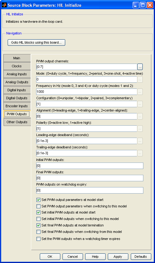
PWM output channels
The PWM output channels to configure. This parameter may be a vector or scalar. The number of PWM outputs available depends on the board selected.
Select a board type from the list for board-specific details: .
PWM output mode
Some cards support different PWM output modes. This parameter allows the PWM output mode to be configured. This parameter may be a vector or scalar. If this parameter has fewer elements than the PWM output channels parameter then the value of the last element will be used for the rest of the PWM output channels. The specified mode must be supported by the card selected on the Main tab.
In PWM mode 0, the PWM outputs have a fixed frequency and varying duty cycle. The PWM inputs to HIL blocks are treated as a duty cycle value between 0.0 (0% duty cycle) and 1.0 (100% duty cycle). The frequency of the PWM output is set using the PWM output frequency or duty cycle parameter.
In PWM mode 1, the PWM outputs have a fixed duty cycle and varying frequency. Not all cards with PWM outputs support this mode. The PWM inputs to HIL blocks are treated as a frequency in Hertz. The duty cycle of the PWM output is set using the PWM output frequency or duty cycle parameter.
In PWM mode 2, the PWM outputs have a fixed duty cycle and varying period. Not all cards with PWM outputs support this mode. The PWM inputs to HIL blocks are treated as a period in seconds. The duty cycle of the PWM output is set using the PWM output frequency or duty cycle parameter.
In PWM mode 3, the PWM outputs is in a one-shot mode. The output works similarly to PWM mode 0 (duty cycle mode) with a fixed frequency and varying period, but only one pulse will be generated per write. Not all cards with PWM outputs support this mode. The PWM inputs to HIL blocks are treated as a duty cycle value between 0.0 (0% duty cycle) and 1.0 (100% duty cycle). The frequency of the PWM output is set using the PWM output frequency or duty cycle parameter.
In PWM mode 4, the PWM outputs have a fixed frequency and varying duty cycle. The PWM inputs to HIL blocks are treated as the active pulse time in seconds. An input of 0 will result in 0% duty cycle, and an input of 1/frequency will result in 100% duty cycle. The frequency is set by the PWM output frequency or duty cycle parameter.
PWM output frequency or duty cycle
This parameter allows the frequency or duty cycle of the PWM outputs to be configured. This parameter may be a vector or scalar. If this parameter has fewer elements than the PWM output channels parameter then the value of the last element will be used for the rest of the PWM output channels. Whether this parameter is interpreted as a frequency or duty cycle depends on the corresponding mode in the PWM output mode parameter.
In PWM mode 0, the PWM outputs have a fixed frequency and varying duty cycle. This parameter determines the frequency of the corresponding PWM output and is specified in Hertz (cycles per second).
In PWM modes 1 and 2, the PWM outputs have a fixed duty cycle and varying frequency. In this case, this parameter determines the duty cycle of the corresponding PWM output and is specified as a fraction between 0.0 (0% duty cycle) and 1.0 (100% duty cycle).
PWM configuration
The PWM configuration determines how the PWM output is configured at the outputs of the data acquistion card. These configurations are briefly described below. For a much more complete discussion, refer to PWM Output Configurations .
In the unipolar configuration (0), the output is a digital pulse train that apppears on a single line. The unipolar configuration is the standard configuration that is familiar to most users. The output varies between 0V and Vcc, where Vcc is the digital power.
The bipolar configuration (1) is similar in that the PWM pulses appear on a single line, but the output is bipolar. The signal levels vary between -V, 0 and +V, where V is either fixed, or programmable. For example, on the QPID card, using the bipolar configuration causes one of the analog outputs to be used for the PWM signal, and the amplitude, V, may be set by writing to that analog output (the amplitude is modulated by the PWM signal). This configuration is unique in that it requires two PWM channels (often the even and odd channel) to produce the bipolar output. The first channel determines the width of the high pulse (0 to V) and the second channel determines the width of the low pulse (0 to -V). The deadband settings may be used to guarantee a gap between the high and low pulses. When marking a PWM channel as bipolar, always mark the secondary channel as unipolar, even though it will actually be used in determining the bipolar output.
In the paired configuration (2), two output lines are used for a single PWM channel. In this configuration the secondary output is identical to the primary output. However, deadband may be introduced using the deadband settings to ensure that the edges of the two signals do not occur at the same time. This configuration may be used for driving 3-phase motors, for example. Typically, if channel N is configured in the paired configuration, then channel N+1 will be used for the secondary output. When marking a PWM channel as paired, always mark the secondary channel as unipolar, even though it will be ignored when determining the secondary output.
The complementary configuration (3) is identical to the paired configuration, except that the secondary output is the inverse of the primary output. The deadband settings also apply. When marking a PWM channel as complementary, always mark the secondary channel as unipolar, even though it will be ignored when determining the secondary output.
PWM alignment
The alignment settings determine how the PWM pulse is aligned within the PWM period. These alignments are briefly described below. For a much more complete discussion, refer to PWM Output Configurations .
In leading-edge alignment (0), the PWM pulse is "left-justified" within the PWM period, with the leading edge of the pulse being aligned to the leading edge of the PWM period (possibly offset by the leading-edge deadband).
In trailing-edge alignment (1), the PWM pulse is "right-justified" within the PWM period, with the trailing edge of the pulse being aligned to the trailing edge of the PWM period (possibly offset by the trailing-edge deadband).
In center alignment (2), the PWM pulse is centered within the PWM period.
PMW polarity
The PWM polarity determines whether the PWM output is active-high (1) or active-low (0). Setting the polarity to active-low will cause the PWM output to be inverted.
Initial PWM outputs
The value(s) to output on the selected PWM output channels when the model is started or when switching to this model dynamically. This parameter may be a vector or scalar. If this parameter has fewer elements than the PWM output channels parameter then the value of the last element will be used for the rest of the PWM output channels. If neither the Set initial PWM outputs at model start nor Set initial PWM outputs when switching to this model parameters are checked then this option is ignored.
For channels in PWM mode 0, this parameter should be specified as a fractional duty cycle with 0.0 representing a 0% duty cycle and 1.0 representing a 100% duty cycle.
For channels in PWM mode 1, this parameter should be specified as a frequency in Hertz (cycles per second).
For channels in PWM mode 2, this parameter should be specified as a period in seconds.
Final PWM outputs
The value(s) to output on the selected PWM output channels when the model is terminated or when switching from this model dynamically. This parameter may be a vector or scalar. If this parameter has fewer elements than the PWM output channels parameter then the value of the last element will be used for the rest of the PWM output channels. If neither the Set final PWM outputs at model termination nor Set final PWM outputs when switching from this model parameters are checked then this option is ignored.
For channels in PWM mode 0, this parameter should be specified as a fractional duty cycle with 0.0 representing a 0% duty cycle and 1.0 representing a 100% duty cycle.
For channels in PWM mode 1, this parameter should be specified as a frequency in Hertz (cycles per second).
For channels in PWM mode 2, this parameter should be specified as a period in seconds.
PWM outputs on watchdog expiry
The value(s) to output on the selected PWM output channels if the watchdog timer expires. The watchdog timer is only used if a HIL Watchdog is present in the model. If this parameter has fewer elements than the PWM output channels parameter then the value of the last element will be used for the rest of the PWM output channels. This parameter is ignored unless the Set the PWM outputs when a watchdog timer expires option is checked.
Set PWM output parameters at model start
Check this option to configure the PWM output mode and frequency or duty cycle for the selected PWM output channels when the model is started. If this option is not checked then the PWM output parameters will not be configured at model start. In this case, either the existing values will be used.
Set PWM output parameters when switching to this model
Check this option to configure the PWM output mode and frequency or duty cycle for the selected PWM outputs when switching to this model using the dynamic reconfiguration capabilities of QUARC. If this option is not checked then the PWM output parameters will not be configured when switching to this model dynamically. In this case, either the existing values will be used. Refer to Dynamic Reconfiguration for more information.
Set initial PWM outputs at model start
Check this option to write the Initial PWM outputs values to the selected PWM outputs when the model is started. If this option is not checked then the PWM outputs will not be written at model start. In this case, the PWM outputs will remain at their current values until the first time they are written by other HIL blocks in the diagram.
Set initial PWM outputs when switching to this model
Check this option to write the Initial PWM outputs values to the selected PWM outputs when switching to this model using the dynamic reconfiguration capabilities of QUARC. If this option is not checked then the PWM outputs will not be written when switching to this model dynamically. In this case, the PWM outputs will remain at their current values until the first time they are written by other HIL blocks in the diagram. Refer to Dynamic Reconfiguration for more information.
Set final PWM outputs at model termination
Check this option to write the Final PWM outputs values to the selected PWM outputs when the model is terminated. If this option is not checked then the PWM outputs will not be written at model termination. In this case, the PWM outputs will remain at their current values.
Set final PWM outputs when switching from this model
Check this option to write the Final PWM outputs values to the selected PWM outputs when switching from this model using the dynamic reconfiguration capabilities of QUARC. If this option is not checked then the PWM outputs will not be written when switching from this model dynamically. In this case, the PWM outputs will remain at their current values. Refer to Dynamic Reconfiguration for more information.
Set the PWM outputs when a watchdog timer expires
Check this option to write the PWM outputs on watchdog expiry values to the selected PWM outputs when the watchdog timer expires. If this option is not checked then the PWM outputs will not be written when the watchdog timer expires. In this case, the PWM outputs will remain at their current values. The watchdog timer is only used if a HIL Watchdog is present in the model. Refer to the HIL Watchdog block for more information.
Other Outputs Pane
The Other Outputs pane of the dialog appears as follows:
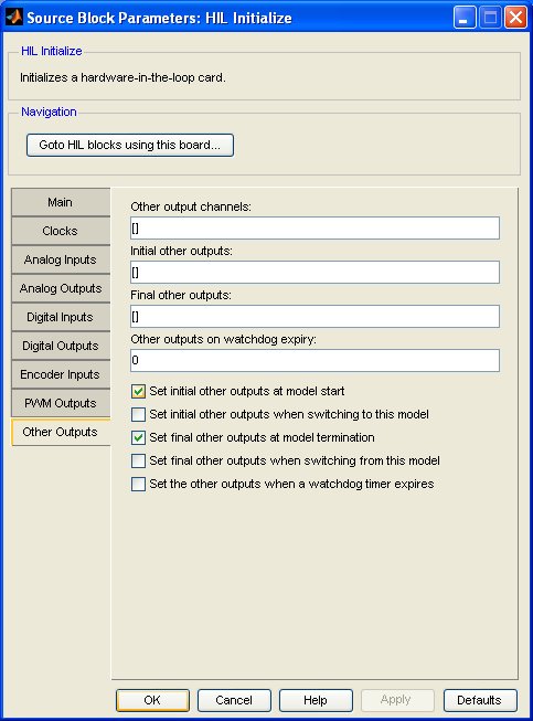
Other output channels
The other output channels to configure. This parameter may be a vector or scalar. The number of other outputs available depends on the board selected. Refer to Channels for general information about other channels in QUARC.
Most boards do not support other channels. Select a board type from the list for board-specific details: .
Initial other outputs
The value(s) to output on the selected other output channels when the model is started or when switching to this model dynamically. This parameter may be a vector or scalar. If this parameter has fewer elements than the Other output channels parameter then the value of the last element will be used for the rest of the other output channels. If neither the Set initial other outputs at model start nor Set initial other outputs when switching to this model parameters are checked then this option is ignored.
Final other outputs
The value(s) to output on the selected other output channels when the model is terminated or when switching from this model dynamically. This parameter may be a vector or scalar. If this parameter has fewer elements than the Other output channels parameter then the value of the last element will be used for the rest of the other output channels. If neither the Set final other outputs at model termination nor Set final other outputs when switching from this model parameters are checked then this option is ignored.
Other outputs on watchdog expiry
The value(s) to output on the selected other output channels if the watchdog timer expires. The watchdog timer is only used if a HIL Watchdog is present in the model. If this parameter has fewer elements than the Other output channels parameter then the value of the last element will be used for the rest of the other output channels. This parameter is ignored unless the Set the other outputs when a watchdog timer expires option is checked.
Set initial other outputs at model start
Check this option to write the Initial other outputs values to the selected other outputs when the model is started. If this option is not checked then the other outputs will not be written at model start. In this case, the other outputs will remain at their current values until the first time they are written by other HIL blocks in the diagram.
Set initial other outputs when switching to this model
Check this option to write the Initial other outputs values to the selected other outputs when switching to this model using the dynamic reconfiguration capabilities of QUARC. If this option is not checked then the other outputs will not be written when switching to this model dynamically. In this case, the other outputs will remain at their current values until the first time they are written by other HIL blocks in the diagram. Refer to Dynamic Reconfiguration for more information.
Set final other outputs at model termination
Check this option to write the Final other outputs values to the selected other outputs when the model is terminated. If this option is not checked then the other outputs will not be written at model termination. In this case, the other outputs will remain at their current values.
Set final other outputs when switching from this model
Check this option to write the Final other outputs values to the selected other outputs when switching from this model using the dynamic reconfiguration capabilities of QUARC. If this option is not checked then the other outputs will not be written when switching from this model dynamically. In this case, the other outputs will remain at their current values. Refer to Dynamic Reconfiguration for more information.
Set the other outputs when a watchdog timer expires
Check this option to write the Other outputs on watchdog expiry values to the selected other outputs when the watchdog timer expires. If this option is not checked then the other outputs will not be written when the watchdog timer expires. In this case, the other outputs will remain at their current values. The watchdog timer is only used if a HIL Watchdog is present in the model. Refer to the HIL Watchdog block for more information.
Targets
|
Target Name |
Compatible* |
Model Referencing |
Comments |
|---|---|---|---|
|
Yes |
Yes |
Fully supported. Some board types may not be supported on this target. |
|
|
Yes |
Yes |
Fully supported. Some board types may not be supported on this target. |
|
|
Yes |
Yes |
||
|
Yes |
Yes |
||
|
Yes |
Yes |
||
|
Yes |
Yes |
||
|
Yes |
Yes |
||
|
Yes |
Yes |
||
|
Yes |
Yes |
||
|
Yes |
Yes |
||
|
Yes |
Yes |
Fully supported. Some board types may not be supported on this target. |
|
|
Yes |
Yes |
||
|
Yes |
Yes |
Fully supported. Some board types may not be supported on this target. |
|
|
Yes |
Yes |
Last fully supported in QUARC 2018. Some board types may not be supported on this target. |
|
|
Rapid Simulation (RSIM) Target |
Yes |
Yes |
Fully supported. Board types are limited to those supported by the host. |
|
S-Function Target |
No |
N/A |
Old technology. Use model referencing instead. |
|
Normal simulation |
Yes |
Yes |
Due to safety and liability concerns, the hardware may not be accessed during normal simulation. |
See Also
Copyright ©2026 Quanser Inc. This page was generated 2026-05-13. Submit feedback to Quanser about this page.
Link to this page.
