
Host Force Feedback Externally-Triggered Condition Force
Produces a condition force effect on a game controller on the host that is triggered by an input signal.
Library
QUARC Targets/Devices/Peripherals/Host/Force Feedback Game Controllers/Condition Force Effects MATLAB Command Line Click to copy the following command line to the clipboard. Then paste it in the MATLAB Command Window: qc_open_library('quarc_library/Devices/Peripherals/Host/Force Feedback Game Controllers/Condition Force Effects')
Description
The Host Force Feedback Externally-Triggered Condition Force block produces a condition force on the host game controller in response to the rising edge of the Trigger input. The block may be configured to stop the effect on the falling edge of the trigger signal. Condition force effects are closed-loop effects that vary according to the "condition" or state of the device, such as its position, velocity or acceleration. The condition force may take the form of a spring, damper, inertia or friction.
Each condition is based on a different "metric". The spring effect uses position as its metric, so the force increases in proportion to the distance of the axis from a defined neutral point. The damper effect uses velocity as its metric, so the force increases in proportion to the velocity with which the user moves the axis. The inertia effect is based on the metric of acceleration, so the force increases in proportion to the acceleration of the axis. Finally, the friction effect is applied when the axis is moved and depends on the defined friction coefficient. In general, excluding saturation, the resulting force is equal to:
negative coefficient * (metric - (offset - deadband))
when the metric is less than offset - deadband, and is equal to:
positive coefficient * (metric - (offset + deadband))
when the metric is greater than offset + deadband.
The Fx, Fy and Fz inputs define a force vector whose direction determines the direction of the condition force applied by the game controller when the offset through dead inputs are scalars. For example, if the Fx and Fy inputs are connected and equal to 1, then a friction effect would resist motion in the northwest-southeast direction but would have no effect on the game controller motion in the northeast-southwest direction. The amplitude and direction of this force are updated every time the trigger occurs, according to the inputs to the block.
If one of the offset through dead inputs is not a scalar, but is a vector whose length equals the number of axes for the effect, then the direction is not determined by the Fx, Fy and Fz inputs. Instead, a separate condition force effect is applied to each axis independently, with the elements of the offset through dead input vectors applying to the corresponding axes. The axes are determined by which of the Fx, Fy and Fz inputs are connected. For example, if the Fx and Fz inputs are connected, but not the Fy input, and the offset through dead inputs are 2-vectors, then the first element of each 2-vector is applied to a condition force effect along the X axis, and the second element to a separate condition force effect along the Z axis. If some of the inputs are scalars, but not all, then the scalar value is applied to all the force effect axes as if the value were expanded into a vector of the appropriate length.
The parameters of the block determine the temporal characteristics of the effect, such as the duration and envelope. A Host Force Feedback Game Controller block must be present in the model to configure the game controller.
Limitations
Unused axes
 Unused axes should be left unconnected or connected to the
Ground
MATLAB Command Line
Click to copy the following command line to the clipboard. Then paste it in the MATLAB Command Window:
doc('Ground') block. Do not connect unused axes to any other type of block because doing so will require a game controller with all
the connected axes. For example, if the Fx, Fy and Fz inputs are all connected then the game controller will need to support all three axes in order for the effect to be rendered.
Unused axes should be left unconnected or connected to the
Ground
MATLAB Command Line
Click to copy the following command line to the clipboard. Then paste it in the MATLAB Command Window:
doc('Ground') block. Do not connect unused axes to any other type of block because doing so will require a game controller with all
the connected axes. For example, if the Fx, Fy and Fz inputs are all connected then the game controller will need to support all three axes in order for the effect to be rendered.
Level of support
Not all force feedback game controllers will support a condition force effect that is triggered by a signal. If externally-triggered condition force effects are supported, a game controller may not support all the axes or features of this block.
Input Ports
Trigger
The signal used to start or stop the effect. Refer to the Trigger mode parameter for details.
Fx
The X component of the direction of the applied force. The positive X direction is from left to right. If this axis is unused, connect it to a Ground MATLAB Command Line Click to copy the following command line to the clipboard. Then paste it in the MATLAB Command Window: doc('Ground') block or leave it unconnected. If one or more of the offset through dead inputs is a vector then the value of this input is not used. However, the fact that it is connected, in this case, indicates that a condition force effect should be applied to the X axis
Fy
The Y component of the direction of the applied force. The positive Y direction is from back to front. If this axis is unused, connect it to a Ground MATLAB Command Line Click to copy the following command line to the clipboard. Then paste it in the MATLAB Command Window: doc('Ground') block or leave it unconnected. If one or more of the offset through dead inputs is a vector then the value of this input is not used. However, the fact that it is connected, in this case, indicates that a condition force effect should be applied to the Y axis
Fz
The Z component of the direction of the applied force. The positive Z direction is from up to down. If this axis is unused, connect it to a Ground MATLAB Command Line Click to copy the following command line to the clipboard. Then paste it in the MATLAB Command Window: doc('Ground') block or leave it unconnected. If one or more of the offset through dead inputs is a vector then the value of this input is not used. However, the fact that it is connected, in this case, indicates that a condition force effect should be applied to the Z axis
offset
The offset by which to bias the metric used to produce the condition effect. For a spring effect, the position at which the spring would be considered at rest is defined by the offset. For a damper, the offset defines the velocity for which the damping force is zero. The offset is not normally used for the inertia or friction effects. See the formulae in the block description above for more details.
+coeff
The proportionality factor that scales the effect with the metric in the positive direction. For the spring effect, it is the spring constant in Hooke's Law. For the damper effect, it is the damping coefficient and for the inertia effect, it is the coefficient applied to acceleration. For the friction effect, it is the coefficient of friction.
For some devices, you can set separate coefficients for the positive and negative direction along the axis associated with the condition. For example, a flight stick controlling a damaged aircraft might move more easily to the right than to the left. If separate coefficients are supported, then this coefficient is applied to the positive direction. Otherwise this coefficient is used for both the positive and negative directions. See the formulae in the block description above for more details.
-coeff
The proportionality factor that scales the effect with the metric in the negative direction. For the spring effect, it is the spring constant in Hooke's Law. For the damper effect, it is the damping coefficient and for the inertia effect, it is the coefficient applied to acceleration. For the friction effect, it is the coefficient of friction.
For some devices, you can set separate coefficients for the positive and negative direction along the axis associated with the condition. For example, a flight stick controlling a damaged aircraft might move more easily to the right than to the left. If separate coefficients are supported, then this coefficient is applied to the negative direction. Otherwise this coefficient is ignored and the +coeff input is used for both the positive and negative directions. See the formulae in the block description above for more details.
+sat
In force feedback, saturation is an expression of the maximum possible force for an effect. For example, suppose a flight stick has a spring condition on the X axis. If the offset is 0 and the coefficient is 1 then the maximum force is exerted when the stick is furthest from the center. But if you define a positive and negative saturation of 0.5 then the force does not increase after the stick has been moved halfway to the right or left. This input is used to specify the saturation in the positive direction. If the device does not support positive and negative saturation limits then this value is applied to both the positive and negative directions. See the formulae in the block description above for more details.
-sat
In force feedback, saturation is an expression of the maximum possible force for an effect. For example, suppose a flight stick has a spring condition on the X axis. If the offset is 0 and the coefficient is 1 then the maximum force is exerted when the stick is furthest from the center. But if you define a positive and negative saturation of 0.5 then the force does not increase after the stick has been moved halfway to the right or left. This input is used to specify the saturation in the negative direction. If the device does not support positive and negative saturation limits then this value is ignored and the +sat input is applied to both the positive and negative directions. See the formulae in the block description above for more details.
dead
The deadband is a zone around the offset of an axis within which the condition is not active. In the case of a spring that is at rest in the middle of an axis, the deadband enlarges this area of rest. See the formulae in the block description above for more details.
Output Ports
This block has no output ports.
Parameters and Dialog Box
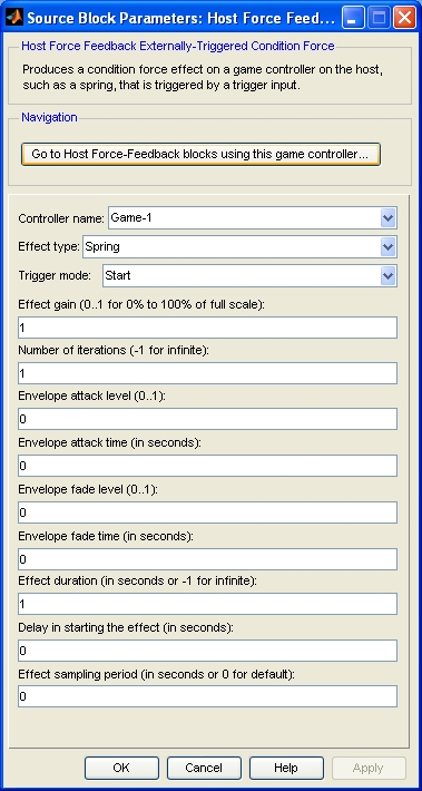
Controller name
The identity of the associated Host Force Feedback Game Controller block. The Host Force Feedback Externally-Triggered Condition Force block must be associated with a Host Force Feedback Game Controller block.
Effect type (tunable offline)
The type of condition effect to generate. The supported types are spring, damper, inertia and friction.
Trigger mode
The function of the trigger input to the block. If this parameter is set to "Start" then a rising edge at the trigger input will start the effect. The effect will stop when the effect duration has expired. A falling edge at the trigger input will be ignored.
If this parameter is set to "Start/Stop" then a rising edge at the trigger input will also start the effect. However, the effect will stop when the effect duration has expired or a falling edge is seen at the trigger input.
Effect gain (tunable online)
A normalized gain to apply to the effect. The forces are scaled by this gain before being applied to the device. The gain must be a fraction between 0 and 1 inclusive. This parameter is useful for scaling effects for a different game controller.
Number of iterations (tunable online)
The number of times to play the effect in sequence. The envelope is re-articulated with each iteration. If this value is -1 then the effect is played indefinitely.
Envelope attack level (tunable online)
The normalized amplitude (0.0=no force, 1.0=maximum) of the force at the beginning of playback.
Envelope attack time (tunable online)
The amount of time in seconds for the amplitude of the effect to ramp linearly from the attack level to the sustain level. The sustain level is the amplitude of the force specified at the block inputs. This parameter may be zero.
Envelope fade level (tunable online)
The normalized amplitude (0.0=no force, 1.0=maximum) of the force at the end of playback.
Envelope fade time (tunable online)
The amount of time in seconds for the amplitude of the effect to ramp linearly from the sustain level to the fade level. The sustain level is the amplitude of the force specified at the block inputs. This parameter may be zero.
Effect duration (tunable online)
The total duration of the effect in seconds. It should be larger than sum of the envelope's attack and fade times. The difference between the effect duration and the sum of the attack and fade times determines the time for which the sustain level is maintained.
Delay in starting the effect (tunable online)
The time in seconds to delay starting the effect after the trigger has occurred.
Effect sampling period (tunable online)
The sampling period of the effect in seconds. This parameter determines the sampling period of the effect on the device itself. It is not related to the sample time of this block. It is the period at which the magnitude of the effect is updated by the device. If this value is zero, the default sampling period is used.
Targets
|
Target Name |
Compatible* |
Model Referencing |
Comments |
|---|---|---|---|
|
Yes |
Yes |
||
|
Yes |
Yes |
||
|
Yes |
Yes |
||
|
Yes |
Yes |
||
|
Yes |
Yes |
||
|
Yes |
Yes |
||
|
Yes |
Yes |
||
|
Yes |
Yes |
||
|
Yes |
Yes |
||
|
Yes |
Yes |
||
|
Yes |
Yes |
||
|
Yes |
Yes |
||
|
Yes |
Yes |
||
|
Yes |
Yes |
Last fully supported in QUARC 2018. |
|
|
Rapid Simulation (RSIM) Target |
Yes |
Yes |
|
|
S-Function Target |
No |
N/A |
Old technology. Use model referencing instead. |
|
Normal simulation |
Yes |
Yes |
See Also
Copyright ©2026 Quanser Inc. This page was generated 2026-05-13. Submit feedback to Quanser about this page.
Link to this page.