Image Transform
Transforms a raw image using the selected transformation algorithm.
Library
QUARC Targets/Image Processing/Generic MATLAB Command Line Click to copy the following command line to the clipboard. Then paste it in the MATLAB Command Window: qc_open_library('quarc_library/Image Processing/Generic')
Description
The Image Transform block transforms a raw image using the selected transformation algorithm. The algorithms are optimized according to the QUARC target and make use of SIMD instructions when available.
The Image Transform block supports both RGB (HxWx3) and grayscale (HxW) inputs. A variety of different input data types are supported that are compatible with The MathWorks' Computer Vision System Toolbox MATLAB Command Line Click to copy the following command line to the clipboard. Then paste it in the MATLAB Command Window: doc vision;, including both integer and floating-point data types.
The transformation algorithms currently supported are enumerated below:
|
Algorithm |
Description |
|---|---|
|
RGB to HSV |
Converts the RGB matrix at the input to an HSV matrix. The HSV matrix is the same size and data type as the input matrix. Hues, saturations and values are all computed to lie within the range of the data type. Hence, for an uint8 RGB matrix input the output hue, saturation and value will range from 0 to 255. |
|
Colorize |
Converts the grayscale matrix at the input to an RGB matrix. This algorithm is intended for colorizing depth images from RGBD cameras. It provides a variety of color themes which are used for mapping luminance values to colors. |
|
Contours |
Converts the grayscale matrix at the input to black and white image of contours, in which each black or white contour region represents the specified distance. This algorithm is intended for viewing depth images from RGBD cameras. It allows small variations in depth to be seen much more readily. |
|
Decolorize |
Converts the RGB matrix at the input to a grayscale matrix. This algorithm is intended for extracting grayscale depth images from a colorized depth image (created using the Colorize algorithm). The color theme plus minimum and maximum pixel values must match the values used when colorizing the depth image in the first place. |
|
Lens undistort |
Corrects for radial and tangential lens distortion of arbitrary order. This algorithm is intended for correcting barrel or pin-cushion distortion in camera lenses, particularly wide-angle lenses such as the ones used on the Quanser QCar. The Brown-Conrady model is used for distortion: xu = xd (1 + K1r2 + K2r4 + ...) + (P1(r2 + 2xd2) + 2P2xdyd)(1 + P3r2 + P4r4 + ...) yu = yd (1 + K1r2 + K2r4 + ...) + (2P2xdyd + P1(r2 + 2y2))(1 + P3r2 + P4r4 + ...) where the coordinates are normalized by the focal length and principal point. The radius, r, is: r2 = xd2 + yd2 Note that the performance of the algorithm is independent of the order of the radial or tangential distortion coefficients. |
|
Remap |
Remaps the input image pixels to arbitrary locations in the output image. The output image may be a different size than the input image. The Row coordinates and Column coordinates parameters provide the mapping from every output pixel to the corresponding input pixel. The dimensions of these two parameters will be the dimensions of the output image.
For example, if the Row coordinates and Column coordinates parameters
are assigned to the variables
when the input is a 480x640 (HxW) image, then the output will be a 240x320 image that is a scaled version of the input that is mirrored vertically. |
|
Reorient |
Reorients the input image by rotating it by a fixed angle about a given origin and translating it to a new origin. The Angle of rotation specifies the angle by which to rotate the image. The Origin of rotation in input image parameter provides the origin about which to rotate the image and the Origin of rotation in output image parameter is where that origin maps to in the output image. The Output width and Output height parameters provide the dimensions of the output image. The image is not scaled. It is only rotated and translated. |
|
Resize |
Resizes the input image. The Output width and Output height parameters provide the resolution of the output image. The output may be larger or smaller than the input image and scaling may be real-valued. |
|
Dither (1-bit) |
Dithers the input image using Floyd-Steinberg dithering to produce a uint8 image with one bit resolution per plane. This transformation is useful for displaying images on black-and-white displays, like the Quanser QCar 2 LCD display. |
Input Ports
image
The input may be an RGB image specified as a three-dimensional MxNx3 matrix where M is the image height and N is the image width. It contains the red, green and blue components for each pixel in the image.
It may also be a grayscale image specified as a two-dimensional MxN matrix. where M is the image height and N is the image width. It contains the luminance for each pixel in the image.
The interpretation of the data depends on the data type. Floating-point types should have elements in the range 0 to 1. Both single and double floating-point types are supported. For integer types, only unsigned integer types are supported. The range of unsigned integer types should be the full range for the integer type.
The input is compatible with The MathWorks' Computer Vision System Toolbox MATLAB Command Line Click to copy the following command line to the clipboard. Then paste it in the MATLAB Command Window: doc vision;.
Output Ports
image
The output data type and dimensions depend on the Algorithm selected, but the output is typically the same data type and dimensions as the input signal.
Parameters and Dialog Box
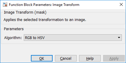
Algorithm
The transformation algorithm to use. The algorithm will determine the data type of the output, and possibly the dimensions.
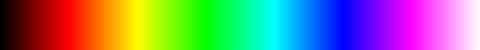
Colorization theme (tunable offline)
Selects the colors to which to map luminance values. The table below shows the currently supported colorization themes. Note that some themes provide greater resolution in the final result than others. All themes provide at least 8-bit resolution so no information is lost for uint8 images. However, for larger input data types some resolution will be lost.
|
Theme |
Colors |
Resolution |
|---|---|---|
|
KRYGCBMW |
|
10.8 |
|
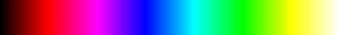
KRMBCGYW |
|
10.8 |
|
KBMRYGCW |
|
10.8 |
|
KBCGYRMW |
|
10.8 |
|
KGCBMRYW |
|
10.8 |
|
KGYRMBCW |
|
10.8 |
|
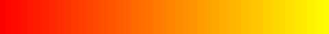
Autumn |
|
8 |
|
Cool |
|
9 |
|
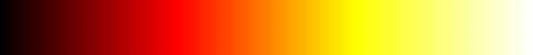
Hot |
|
9.6 |
|
Spring |
|
8 |
|
Summer |
|
8 |
|
Winter |
|
8 |
Minimum pixel value (tunable online)
The minimum value of a pixel when colorizing a grayscale image. Pixels below this value will map to the first color in the output color map.
Maximum pixel value (tunable online)
The maximum value of a pixel when colorizing a grayscale image. Pixels above this value will map to the last color in the output color map.
Contour depth (tunable online)
The depth of each contour line in input image units. For example, for a uint16 depth image, a value of 1 will show the smallest distinctions in depth. For a single depth image, a value of 1/65536 may be more appropriate if the depth camera has 16-bit resolution. For single images representing actual distance in meters, then specify the contour depth in meters, such as 0.01.
Focal length (tunable offline)
The focal length of the camera. This parameter may be specified as a scalar, in which case the value is applied in both the row and column direction, or as a 2-vector [r,c] to specify the focal length in the row and column directions individually.
Principal point (tunable offline)
The principal point or center of distortion for the camera. This parameter must be a 2-vector: [r,c]. The r coordinate is the row number and the c coordinate is the column number.
Radial distortion coefficient (tunable offline)
A vector containing the radial distortion coefficients, K = [k1 k2 ...]. If this parameter is empty then no radial distortion correction will be applied. In this case, only the tangential distortion correction will be applied.
Tangential distortion coefficient (tunable offline)
A vector containing the tangential distortion coefficients, P = [P1 P2 ...]. If this parameter is empty then no tangential distortion correction will be applied. In this case, only the radial distortion correction will be applied.
Extrapolated pixel value (tunable online)
A scalar or 3-vector containing the pixel value to use for output pixels that have no corresponding pixel in the input image. A scalar value represents a luminance and will be applied equally to all colour planes if the input is RGB. A 3-vector represents an [R,G,B] colour value. If the input is grayscale then the corresponding luminance will be applied.
Interpolation method (tunable offline)
The interpolation method to use when mapping pixels from the input image to the output image. Nearest neighbour interpolation is typically fastest but can produce a less accurate result. Linear interpolation provides a more accurate result but is generally slower.
Row coordinates
The row coordinate of each output pixel in the input image. The column coordinate comes from the corresponding element in the Column coordinates parameter. For example, if the (i,j) element of the row coordinate matrix is r, and (i,j) element of the column coordinate matrix is c, then the (i,j) output pixel will be copied from the (r,c) element of the input image. If r and c are real numbers rather than integers then the (i,j) output depends on the Interpolation method parameter. Nearest neighbour interpolation will use the (round(r), round(c)) element of the input image. Linear interpolation will do a weighted average of the pixels overlapping (r,c) i.e., the (floor(r), floor(c)), (floor(r) + 1, floor(c)), (floor(r), floor(c) + 1) and (floor(r) + 1, floor(c) + 1) pixels of the input image.
This parameter must be a 2D matrix whose dimensions determine the width and height of the output image. Its dimensions must match the Column coordinates parameter. The input image determines whether the output is grayscale or RGB.
Column coordinates
The column coordinate of each output pixel in the input image. The row coordinate comes from the corresponding element in the Row coordinates parameter. For example, if the (i,j) element of the row coordinate matrix is r, and (i,j) element of the column coordinate matrix is c, then the (i,j) output pixel will be copied from the (r,c) element of the input image. If r and c are real numbers rather than integers then the (i,j) output depends on the Interpolation method parameter. Nearest neighbour interpolation will use the (round(r), round(c)) element of the input image. Linear interpolation will do a weighted average of the pixels overlapping (r,c) i.e., the (floor(r), floor(c)), (floor(r) + 1, floor(c)), (floor(r), floor(c) + 1) and (floor(r) + 1, floor(c) + 1) pixels of the input image.
This parameter must be a 2D matrix whose dimensions determine the width and height of the output image. Its dimensions must match the Row coordinates parameter. The input image determines whether the output is grayscale or RGB.
Angle of rotation (tunable offline)
The angle by which to rotate the image in radians. This parameter is a scalar.
Origin of rotation in input image (tunable offline)
The origin of rotation as a a 2-vector, (r,c), in the input image. The r-coordinate is the row and the c-coordinate is the column.
Origin of rotation in output image (tunable offline)
The origin of rotation as a a 2-vector, (r,c), in the output image. The r-coordinate is the row and the c-coordinate is the column. This parameter determines how the origin of rotation in the source image maps to the output image. It can be used to translate the input image.
Output height
The height or number of rows of the output image.
Output width
The width or number of columns of the output image.
Targets
|
Target Name |
Compatible* |
Model Referencing |
Comments |
|---|---|---|---|
|
Yes |
Yes |
||
|
Yes |
Yes |
||
|
Yes |
Yes |
||
|
Yes |
Yes |
||
|
Yes |
Yes |
||
|
Yes |
Yes |
||
|
Yes |
Yes |
||
|
Yes |
Yes |
||
|
Yes |
Yes |
||
|
Yes |
Yes |
||
|
Yes |
Yes |
||
|
Yes |
Yes |
||
|
Yes |
Yes |
||
|
Yes |
Yes |
Last fully supported in QUARC 2018. |
|
|
Rapid Simulation (RSIM) Target |
Yes |
Yes |
|
|
S-Function Target |
No |
N/A |
Old technology. Use model referencing instead. |
|
Normal simulation |
Yes |
Yes |
Copyright ©2026 Quanser Inc. This page was generated 2026-05-13. Submit feedback to Quanser about this page.
Link to this page.