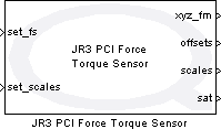

JR3 PCI Force Torque Sensor
| This block has been deprecated and should not be used in new models. To inquire about alternatives to using this block, please contact Quanser at tech@quanser.com. |
Measures forces and moments of inertia along X, Y, and Z axes using the JR3 PCI sensor.
Library
QUARC Targets Deprecated/Devices/Third-Party/JR3 MATLAB Command Line Click to copy the following command line to the clipboard. Then paste it in the MATLAB Command Window: qc_open_library('quarc_library_deprecated/Devices/Third-Party/JR3')
Description

The JR3 PCI Force Torque Sensor block measures forces and moments of inertia along the X, Y, and Z axes. This block interfaces with a single DSP, single channel JR3 sensor connected to the PC via a JR3 PCI receiver card. Currently, the block has been tested with a JR3 M-series force-torque sensor and a JR3 single-channel PCI receiver. This block should support all standard JR3 sensors so long as they are connected using a JR3 PCI receiver card.
The JR3 sensor operates an onboard DSP at 8kHz, and provides low pass filtering of the raw force data at several cutoff frequencies. The JR3 PCI Force Torque Sensor block allows the user to dynamically set the full scales of the device, which gives the user control over the range and resolution of the raw sensor measurements. A saturation vector is also given to indicate when a measurement has saturated at the full scale value; this depends on the magnitude of the measurement and the setting of the full scales of the device.
To operate a JR3 sensor, code must first be downloaded to the DSP on the sensor. The DSP code comes
in a file named jr3pci.idm and must be in the directory in which the model is running. The
JR3 PCI Force Torque Sensor block checks the sensor's COUNT_X counter to determine if the DSP is already running.
If the counter has changed after 10ms then the DSP is considered to be running and the code is not
downloaded to the DSP. If the counter has not changed then the DSP is assumed to be inactive and the
DSP is restarted at which point the code is then downloaded to the DSP.
Input Ports
set_fs
A boolean value indicating whether the full scales should be set to the given second input value.
If this value is true then the block will take the values given in the fs input and use them
to set the full scales of the JR3 sensor.
set_scales
A 6-vector of type int16 representing the full scales for the X, Y, and Z axis forces and the
X, Y, and Z axis moments, respectively. Decoupled and filtered data is scaled so that ±16384 is equal
to the full scales. Refer to the JR3 manuals for detailed information on setting full scale values.
Output Ports
xyz_fm
A 6-vector output of type int16 containing the X, Y, and Z axis force measurements and moment
measurements, i.e., [fx, fy, fz, mx, my, mz], where fi and mi represent the force
and moment measurements for axis i. The data is scaled so that ±16384 is equal to the full scales.
offsets
A 6-vector of type int16 containing the offsets for the X, Y, and Z axis forces and the X, Y, and
Z axis moments, respectively. These values represent the current values being used by the JR3 sensor.
scales
A 6-vector of type int16 representing the full scales for the X, Y, and Z axis forces and the X, Y,
and Z axis moments, respectively. These values represent the current values being used by the JR3 sensor.
sat
A 6-vector of type boolean used to indicate if any of the sensors become saturated. The values in
the vector correspond to the X, Y, and Z axis forces and the X, Y, and Z axis moments, respectively.
Parameters and Dialog Box

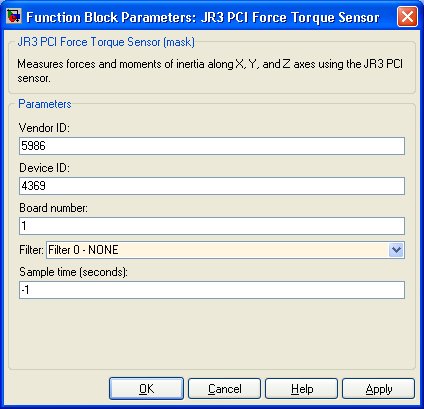
 Note that the Vendor ID and Device ID parameters given in the JR3 test application are hexadecimal (base-16)
numbers and the parameters for the block are given in decimal (base-10) numbers. For example, the JR3 test
application gives a vendor ID of 0x1762 and a device ID of 0x1111, which means the vendor ID and device ID in
decimal are 5986 and 4369, respectively.
Vendor ID
The vendor ID of the JR3 sensor being used. Refer to the JR3 sensor documentation to determine the correct vendor ID for your sensor.
Device ID
The device ID of the JR3 sensor being used. Refer to the JR3 sensor documentation to determine the correct device ID for your sensor.
Board number
The JR3 PCI board being used. This number ranges from 1 up to the number of JR3 PCI boards installed on the PC.
Filter
The JR3 device can perform low pass filtering on the raw sensor data. A filter value of 0 indicates no filtering should be applied. For a typical sensor with a sample rate of 8kHz, a filter value of 1 indicates a filter with a cutoff frequency of 500Hz will be used. Each succeeding filter has a cutoff frequency of 1/4 of the preceding filter.
Sample time
The sample time of the block. A sample time of 0 indicates that the block will be treated as a continuous time block. A positive sample time indicates that the block is a discrete time block with the given sample time.
To use the fundamental sampling time of the model, set the sample time to qc_get_step_size, which is a QUARC function that returns the fundamental sampling time of the model.
A sample time of -1 indicates that the block inherits its sample time from its inputs. The default sample time is set to -1.
Targets
|
Target Name |
Compatible* |
Model Referencing |
Comments |
|---|---|---|---|
|
Yes |
Yes |
||
|
No |
No |
Not supported. |
|
|
Yes |
Yes |
||
|
Yes |
Yes |
||
|
Yes |
Yes |
||
|
Yes |
Yes |
||
|
Yes |
Yes |
||
|
Yes |
Yes |
||
|
Yes |
Yes |
||
|
Yes |
Yes |
||
|
No |
No |
Not supported. |
|
|
Yes |
Yes |
||
|
No |
No |
Not supported. |
|
|
No |
No |
Not supported. |
|
|
Rapid Simulation (RSIM) Target |
No |
No |
Not supported. |
|
S-Function Target |
No |
N/A |
Old technology. Use model referencing instead. |
|
Normal simulation |
Yes |
Yes |

Copyright ©2025 Quanser Inc. This page was generated 2025-11-01. Submit feedback to Quanser about this page.
Link to this page.