
Kinova 4-DOF MICO Read
Reads the Joint Control Robot - 4 DOF joint angular positions, velocities, currents, torques, temperatures and states.
Library
QUARC Targets/Devices/Third-Party/Kinova/Robots/4-DOF MICO MATLAB Command Line Click to copy the following command line to the clipboard. Then paste it in the MATLAB Command Window: qc_open_library('quarc_library/Devices/Third-Party/Kinova/Robots/4-DOF MICO')
Description
The Kinova 4-DOF MICO Read block is used to read the joint angles, speeds, currents, torques, temperatures and error signals from the Joint Control Robot - 4 DOF. Only one set of the Kinova 4-DOF MICO Read, Kinova 4-DOF MICO Write, and Kinova 4-DOF MICO Torque Reset blocks is allowed in a model.
Limitations
CAUTION: Open Architecture Robot!
 When using this block, the Joint Control Robot - 4 DOF becomes an open architecture system.
This block is intended for mature and experienced engineers only!
The user must understand the difference between an industrial controller and an open architecture controller.
If it is unclear contact Quanser immediately at tech@quanser.com.
When using this block, the Joint Control Robot - 4 DOF becomes an open architecture system.
This block is intended for mature and experienced engineers only!
The user must understand the difference between an industrial controller and an open architecture controller.
If it is unclear contact Quanser immediately at tech@quanser.com.
The user is solely responsible for the implementation of the open architecture controller! Quanser and Kinova are not responsible for any material or bodily damage that ensues from the use of this equipment.
Do not approach the robot when the arm or the controller are powered up! Install the robot in a safe location and ensure no personnel approaches the robot while it is in operation or while the arm is powered.
All software using this block supplied by Quanser is only to be considered a sample and should not be used on a regular basis. The user should write their own open-architecture control software.
Fully read this document as well as the Kinova 4-DOF MICO Write block documentation before connecting the QUARC external PC to the Joint Control Robot - 4 DOF.
Robot Limitations
The Joint Control Robot - 4 DOF is designed to operate within specific velocity and current limitations.
When designing and implementing controllers, the user is responsible to properly generate and regulate the position setpoints and commands
(and their rate of change) so that the Joint Control Robot - 4 DOF stays within its operational limits.
Serial Communication Rate Limitations
The communication to the Joint Control Robot - 4 DOF is carried out by a dedicated, high-priority and asynchronous thread,
which executes independently of the QUARC model thread.
The communication cycle time (a.k.a., period) over the RS-485 serial bus of the Joint Control Robot - 4 DOF takes approximately 1.2 ms.
Installation Requirements
Open-Architecture 4-DOF MICO or JACO Robot
 This blockset requires a customized 4-DOF MICO or JACO (Gen2) robot from Kinova explicitly for use with QUARC,
and equipped with a 2-finger gripper module at the end of the arm.
QUARC interfaces to the Joint Control Robot - 4 DOF via two RS-485 channels, allowing open-architecture control of the robot.
This blockset requires a customized 4-DOF MICO or JACO (Gen2) robot from Kinova explicitly for use with QUARC,
and equipped with a 2-finger gripper module at the end of the arm.
QUARC interfaces to the Joint Control Robot - 4 DOF via two RS-485 channels, allowing open-architecture control of the robot.
Serial Controller Card
The robot arm communicates with the QUARC PC (i.e., the QUARC target machine which is running the QUARC model)
via a specialized high-speed RS-485 dual-port serial adapter.
Specifically, the target PC (used by the Kinova 4-DOF MICO Read block) must have the
Fastcom: FSCC RS485 Communications Adapter (PCI card), from Commtech Inc.,
to interface with the Joint Control Robot - 4 DOF.
To properly install the FSCC serial controller card into the QUARC PC,
follow exactly the installation steps described in the "Set-Up" section of the Quanser "Joint Control Robot - 4 DOF: User Manual".
Contact Quanser at tech@quanser.com for more details, as needed.
Input Ports
This block has no input ports.
Output Ports
4-DOF MICO
A reference to the Joint Control Robot - 4 DOF that must be connected to the 4-DOF MICO input port of the Kinova 4-DOF MICO Write block. Failure to connect this signal to the Kinova 4-DOF MICO Write block will result in an error being generated.
joint angles
A 6-element vector of double values containing the angular positions for the four (4) joints and two (2) fingers of the Joint Control Robot - 4 DOF. SI units are used and the 4 robot joint angle values are provided in radians (rad). The finger 2 angular position measurements have no unit and are reset to zero when the robot is power-cycled. Afterwards, the finger output angles are with respect to their powered-on zero position.
joint velocities
A 6-element vector of double values containing the angular velocities for the four (4) joints and two (2) fingers of the Joint Control Robot - 4 DOF. SI units are used and the robot 4 joint velocity values are provided in radians per second (rad/s).
motor currents
A 6-element vector of double values containing the motor currents for the 4 joint and 2 finger motors of the Joint Control Robot - 4 DOF. The robot motor currents are provided in Amperes (A). Refer to Kinova 4-DOF MICO Write block limitation for the maximum repetitive current for each joint.
joint torques
A 4-element vector of double values containing the torques of the robot 4 joints. SI units are used and the robot joint torque values are provided in Newtons metres (N.m). Refer to Kinova 4-DOF MICO Torque Reset block if the torque sensor readings do not look correct (e.g. torque sensor readings are not 0 when the robot is in the neutral position), and torque sensors recalibration is needed.
joint temperatures
A 6-element vector of double values containing the temperatures for the 4 joint and 2 finger actuators of the Joint Control Robot - 4 DOF. The robot motor temperatures are provided in degrees Celsius (C). Refer to Kinova 4-DOF MICO Write block limitation for the maximum temperature for each joint.
fingers min/max
A 4-element vector of double values containing the minimum and maximum position limits for each of the two fingers, respectively. The minimum finger position corresponds to the fully open position. This output only shows the minimum and maximum position limits, i.e., [F1min, F1max, F2min, F2max], when the MICO gripper fingers have been calibrated for the first time after the MICO arm has been powered on. This output shows a value of [0.0, 0.0, 0.0, 0.0] otherwise.
joint errors
A 6-element vector of uint32 values containing the error codes for the 4 joint and 2 finger actuators of the Joint Control Robot - 4 DOF. The table below gives a description of the possible error code values.
|
Error Code |
Error Description |
|---|---|
|
0x0000 |
No error |
|
0x0001 |
Initialization error |
|
0x0002 |
Firmware version error |
|
0x0004 |
RS-485 communication error |
|
0x0008 |
Setting position PID gains error |
|
0x0010 |
Temperature error |
|
0x0020 |
Velocity error (torque mode) |
|
0x0040 |
Position limit error (torque mode) |
|
0x0080 |
Absolute position error |
|
0x0100 |
Relative position error |
|
0x0200 |
Command error |
|
0x0400 |
Current error |
|
0x0800 |
Torque / Inactivity time error (torque mode) |
joint control modes
A 6-element vector of uint8 values containing the control mode values for the 4 joint and 2 finger actuators of the Joint Control Robot - 4 DOF.
The possible control modes (and corresponding values) are the Finger Calibration Control Mode (0), Position Control Mode (1) or Torque Control Mode (2), as detailed in the table below. Only the 4 joint actuators can be operated in Torque Control Mode, the 2 fingers cannot.
|
Control Mode Description |
joint control mode Value |
|---|---|
|
Finger Calibration Control Mode |
0 |
|
Position Control Mode |
1 |
|
Torque Control Mode |
2 |
period
A double value representing the communication loop time (including RS-485 serial bus communication delays) in seconds (s) between when the Kinova 4-DOF MICO Write block input data are sent to the robot and when the robot data are received. As long as the period value changes and is updated, the communication is active and the Quanser QUARC application is connected.
Parameters and Dialog Box
Individual Panes
Main Pane
The Main pane of the dialog appears as follows:
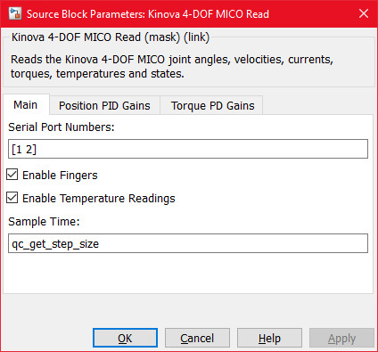
Serial Port Numbers
A 2-element vector of integers indicating the two serial port numbers (of the FSCC RS-485 adapter) used to connect to the Joint Control Robot - 4 DOF's channel 1 and channel 2 connectors, respectively. In Windows, the serial port number is appended to the string "COM" to form the name of the port.
Enable Fingers
A checkbox that enables use of the Joint Control Robot - 4 DOF fingers. If this parameter is not selected (i.e., disabled), the Joint Control Robot - 4 DOF fingers are not initialized, no commands are sent to the fingers and no status data are read from them. Disabling the fingers reduces the communication load to the MICO robot and decreases the communication cycle time (a.k.a., period).
Enable Temperature Readings
A checkbox that enables reading the joint temperatures of the Joint Control Robot - 4 DOF. If this parameter is not selected (i.e., disabled), the Joint Control Robot - 4 DOF temperatures are not read. Disabling the temperature readings reduces the communication load to the MICO robot and decreases the communication cycle time (a.k.a., period).
Sample Time
The sample time of the block. A sample time of 0 indicates that the block will be treated as a continuous time block. A positive sample time indicates that the block is a discrete time block with the given sample time.
A sample time of -1 indicates that the block inherits its sample time. Since this is a source block, only inherent the sample time when it is placed in a conditionally executed subsystem, like a Triggered or Enabled Subsystem, or in a referenced model.
To use the fundamental sampling time of the model, set the sample time to qc_get_step_size, which is a QUARC function that returns the fundamental sampling time of the model.
Position PID Gains Pane
The Position PID Gains pane of the dialog appears as follows:
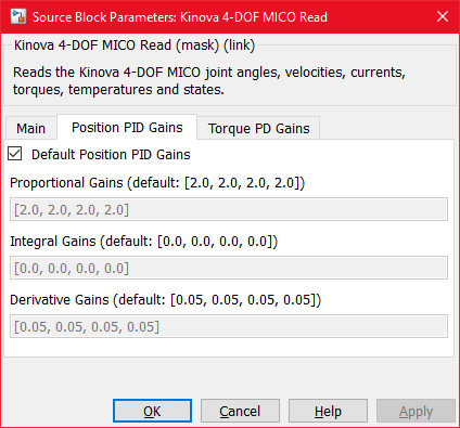
Default Position PID Gains
When this checkbox is checked, the position Proportional-Integral-Derivative (PID) gains for each of the four Joint Control Robot - 4 DOF joint PID position controllers are reset to their default values, and the Proportional Gains, Integral Gains and Derivative Gains entry field parameters are disabled.
When this checkbox is unchecked, the Proportional Gains, Integral Gains and Derivative Gains entry field parameters are enabled. The user can then edit and change the robot corresponding position PID gains, which are set at system initialization.
Proportional Gains
A 4-element vector of double values containing the position Proportional (P) gains for each of the robot 4 joint PID position controllers. This parameter is enabled, and the proportional gain values can be changed, when the Default Position PID Gains checkbox is unchecked.
When the Default Position PID Gains checkbox is checked, all the position proportional gains are set to their default values. The table below indicates the default proportional gain values for each joint of the Joint Control Robot - 4 DOF.
|
Joint #1 |
Joint #2 |
Joint #3 |
Joint #4 |
|
|---|---|---|---|---|
|
Default Position Proportional Gain |
2.0 |
2.0 |
2.0 |
2.0 |
Integral Gains
A 4-element vector of double values containing the position Integral (I) gains for each of the robot 4 joint PID position controllers. This parameter is enabled, and the integral gain values can be changed, when the Default Position PID Gains checkbox is unchecked.
When the Default Position PID Gains checkbox is checked, all the position integral gains are set to their default values. The table below indicates the default integral gain values for each joint of the Joint Control Robot - 4 DOF.
|
Joint #1 |
Joint #2 |
Joint #3 |
Joint #4 |
|
|---|---|---|---|---|
|
Default Position Integral Gain |
0.0 |
0.0 |
0.0 |
0.0 |
Derivative Gains
A 4-element vector of double values containing the position Derivative (D) gains for each of the robot 4 joint PID position controllers. This parameter is enabled, and the derivative gain values can be changed, when the Default Position PID Gains checkbox is unchecked.
When the Default Position PID Gains checkbox is checked, all the position derivative gains are set to their default values. The table below indicates the default derivative gain values for each joint of the Joint Control Robot - 4 DOF.
|
Joint #1 |
Joint #2 |
Joint #3 |
Joint #4 |
|
|---|---|---|---|---|
|
Default Position Derivative Gain |
0.05 |
0.05 |
0.05 |
0.05 |
Torque PD Gains Pane
The Torque PD Gains pane of the dialog appears as follows:
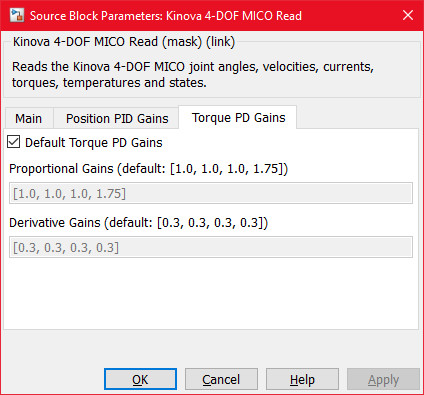
Default Torque PD Gains
When this checkbox is checked, the torque Proportional-Derivative (PD) gains for each of the four Joint Control Robot - 4 DOF joint PD torque controllers are reset to their default values, and the Proportional Gains and Derivative Gains entry field parameters are disabled.
When this checkbox is unchecked, the Proportional Gains and Derivative Gains entry field parameters are enabled. The user can then edit and change the robot corresponding PD gains, which are set at system initialization.
Proportional Gains
A 4-element vector of double values containing the torque Proportional (P) gains for each of the robot 4 joint PD torque controllers. This parameter is enabled, and the proportional gain values can be changed, when the Default Torque PD Gains checkbox is unchecked.
When the Default Torque PD Gains checkbox is checked, all the torque proportional gains are set to their default values. The table below indicates the default proportional gain values for each joint of the Joint Control Robot - 4 DOF.
|
Joint #1 |
Joint #2 |
Joint #3 |
Joint #4 |
|
|---|---|---|---|---|
|
Default Torque Proportional Gain |
1.0 |
1.0 |
1.0 |
1.75 |
Derivative Gains
A 4-element vector of double values containing the torque Derivative (D) gains for each of the robot 4 joint PD torque controllers. This parameter is enabled, and the derivative gain values can be changed, when the Default Torque PD Gains checkbox is unchecked.
When the Default Torque PD Gains checkbox is checked, all the torque derivative gains are set to their default values. The table below indicates the default derivative gain values for each joint of the Joint Control Robot - 4 DOF.
|
Joint #1 |
Joint #2 |
Joint #3 |
Joint #4 |
|
|---|---|---|---|---|
|
Default Torque Derivative Gain |
0.3 |
0.3 |
0.3 |
0.3 |
Targets
|
Target Name |
Compatible* |
Model Referencing |
Comments |
|---|---|---|---|
|
Yes |
Not supported in a referenced model. Use in top-level model only. |
||
|
Yes |
Not supported in a referenced model. Use in top-level model only. |
||
|
No |
No |
||
|
No |
No |
||
|
No |
No |
||
|
No |
No |
||
|
No |
No |
||
|
No |
No |
||
|
No |
No |
||
|
No |
No |
||
|
No |
No |
||
|
No |
No |
||
|
No |
No |
||
|
No |
No |
Last fully supported in QUARC 2018. |
|
|
Rapid Simulation (RSIM) Target |
No |
No |
|
|
S-Function Target |
No |
N/A |
Old technology. Use model referencing instead. |
|
Normal simulation |
No |
No |
Copyright ©2026 Quanser Inc. This page was generated 2026-05-13. Submit feedback to Quanser about this page.
Link to this page.