
LED Strip
Writes to an LED strip.
Library
QUARC Targets/Devices/Third-Party/Displays MATLAB Command Line Click to copy the following command line to the clipboard. Then paste it in the MATLAB Command Window: qc_open_library('quarc_library/Devices/Third-Party/Displays')
Description
The LED Strip block controls an LED strip. The LEDs may be controlled individually or as a group. Different modes are also supported for creating special effects.
The LED Strip assumes that the LED strip is connected to the target using an SPI MOSI line. To identify the communications protocol with which to communicate with the LED strip, the block takes a URI as an argument. Universal Resource Identifiers (URI), such as spi://localhost:1?memsize=420,word=8,baud=3333333,lsb=off,frame=1, are used by QUARC for all its communications because it provides a uniform, extensible and flexible means of identifying the communication protocol to use and the associated communication parameters. Refer to Universal Resource Identifiers for more information.
The block accepts either a 3xN matrix as input or three vectors. To have vector inputs, check the Vector inputs option in the dialog parameters. For vector inputs, the three inputs represent the red, green and blue components of the LED colors respectively. For a matrix input, each column represents the red, green and blue components of the LED color for the LED corresponding to that column. The inputs may be variable-size. Refer to Variable-Size Signals for more information on variable-size signals.
QUARC provides a convenient Color Constant block for specifying colors in a Simulink model.
The maximum number of LEDs in the strip is specified via the Maximum number of LEDs parameter. The size of the input cannot exceed the maximum number of LEDs.
The data type of the input(s) determines how the color components are interpreted. The supported data types are double, single, uint8, uint16, uint32 and boolean. For the floating-point types, color component values range from 0.0 to 1.0. For the unsigned integer types, color component values range from 0 to the maximum unsigned integer value for that type. Boolean values are interpreted as either 0.0 or 1.0 so only primary colors will be achievable in that case.
The LED Strip block supports several display modes: individual, uniform and circulating. In individual mode, each LED in the strip may be independently controlled. If there are N columns in the input then the first N LEDs will be controlled. The rest of the LEDs will be left untouched. This can yield some interesting effects if variable-size signals are used.
In uniform mode, all the LEDs are controlled. If there are N columns in the input then the first N LEDs will be controlled according to the N columns of the input. The remaining LEDs will be controlled according to the Nth column as well. Hence, if N is 1 then all the LEDs will be driven with the same color.
Finally, in circulating mode, all the LEDs are also controlled. If there are N columns in the input then N LEDs will be controlled according to the N columns of the input. However, rather than controlling the first N LEDs, the set of contiguous LEDs controlled shifts by one LED each time the block is executed. Hence, if N is 1 then one LED will be controlled and it will appear to circulate around the LED strip, moving from the first LED one-by-one to the last LED and then back to the first LED continuously.
Use the Initial values to specify the color of all the LEDs when the model starts. Then use the Final values to specify the color of all the LEDs when the model stops. For both sets of parameters, the last element of each vector will be used for the remaining LEDs if the vectors are shorted than the maximum number of LEDs. The vector elements are expected to be color component values according to their data type, just like the inputs. Typically, these parameters are doubles so the color components should range from 0.0 to 1.0.
Input Ports
colors
A fixed or variable-sized 3xN matrix signal containing the color components for each LED. The first row contains the red color component, the second row the green and the third row the blue color component. Each column contains the color for the corresponding LED in the strip. This input is only available when the Vector inputs option is unchecked. Only the number of columns may vary when the input is variable-sized.
r
A fixed or variable-sized vector containing the red color component for the corresponding LED. This input is only available when the Vector inputs option is checked.
g
A fixed or variable-sized vector containing the green color component for the corresponding LED. This input is only available when the Vector inputs option is checked.
b
A fixed or variable-sized vector containing the blue color component for the corresponding LED. This input is only available when the Vector inputs option is checked.
Output Ports
err
Indicates whether an error occurred while writing to the LED strip. If an error occurred, it will be a negative QUARC error code. Otherwise the number of bytes written to the LED strip will be output.
Data Type Support
The input(s) only accept double, single, uint8, uint16, uint32 or boolean signals. The input(s) may be variable-sized. Refer to Variable-Size Signals for more information on variable-size signals.
Parameters and Dialog Box
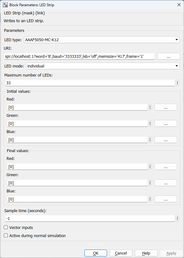
LED type
The type of LED strip.
URI (tunable offline)
The URI indicating the protocol with which to communicate with the LED strip. Refer to Universal Resource Identifiers for more information about URIs and the communications protocols supported by QUARC.
Suitable URIs for the built-in LED strip on the following platforms are listed below:
|
Platform |
Display Type |
URI |
|---|---|---|
|
QCar 2 |
AAAF5050-MC-K12 |
spi://localhost:1?memsize=420,word=8,baud=3333333,lsb=off,frame=1 |
LED mode
The LED mode to use: individual, uniform or circulating. In individual mode, each LED in the strip may be independently controlled. If there are fewer columns in the input than LEDs to control then the remaining LEDs are left untouched.
In uniform mode, all the LEDs are controlled. If there are fewer columns in the input than LEDs to control then the remaining LEDs are set to the color of the last column provided.
In circulating mode, the LEDs are controlled similarly to individual mode except that the set of LEDs controlled is shifted by one each time the block is executed so that the LEDs appear to circulate around the LED strip.
Initial values / Red (tunable offline)
The red component of the color to which the LEDs are set when the model starts. If fewer elements are provided than the maximum number of LEDs than the last element provided is used for the remaining LEDs. The vector elements are expected to be color component values according to their data type, just like the inputs. Typically, these parameters are doubles so the color components should range from 0.0 to 1.0.
Press the browse button next to the edit field to add a color using a color dialog.
Initial values / Green (tunable offline)
The green component of the color to which the LEDs are set when the model starts. If fewer elements are provided than the maximum number of LEDs than the last element provided is used for the remaining LEDs. The vector elements are expected to be color component values according to their data type, just like the inputs. Typically, these parameters are doubles so the color components should range from 0.0 to 1.0.
Press the browse button next to the edit field to add a color using a color dialog.
Initial values / Blue (tunable offline)
The blue component of the color to which the LEDs are set when the model starts. If fewer elements are provided than the maximum number of LEDs than the last element provided is used for the remaining LEDs. The vector elements are expected to be color component values according to their data type, just like the inputs. Typically, these parameters are doubles so the color components should range from 0.0 to 1.0.
Press the browse button next to the edit field to add a color using a color dialog.
Final values / Red (tunable online)
The red component of the color to which the LEDs are set when the model stops. If fewer elements are provided than the maximum number of LEDs than the last element provided is used for the remaining LEDs. The vector elements are expected to be color component values according to their data type, just like the inputs. Typically, these parameters are doubles so the color components should range from 0.0 to 1.0.
Press the browse button next to the edit field to add a color using a color dialog.
Final values / Green (tunable online)
The green component of the color to which the LEDs are set when the model stops. If fewer elements are provided than the maximum number of LEDs than the last element provided is used for the remaining LEDs. The vector elements are expected to be color component values according to their data type, just like the inputs. Typically, these parameters are doubles so the color components should range from 0.0 to 1.0.
Press the browse button next to the edit field to add a color using a color dialog.
Final values / Blue (tunable online)
The blue component of the color to which the LEDs are set when the model stops. If fewer elements are provided than the maximum number of LEDs than the last element provided is used for the remaining LEDs. The vector elements are expected to be color component values according to their data type, just like the inputs. Typically, these parameters are doubles so the color components should range from 0.0 to 1.0.
Press the browse button next to the edit field to add a color using a color dialog.
Sample time
The sample time of the block. A sample time of 0 indicates that the block will be treated as a continuous time block. A positive sample time indicates that the block is a discrete time block with the given sample time.
A sample time of -1 indicates that the block inherits its sample time from the input. The block inherits the sample time by default.
To set the sample time to the fundamental sampling time of the model, use the qc_get_step_size function, which is a QUARC function that returns the fundamental sampling time of the model. The fundamental sampling time of the model is the sampling time entered in the Fixed step size field of the Solver pane of the Configuration parameters dialog.
Vector inputs
Check this option to enable the color components to be specified using separate red, green and blue vector inputs. If this option is unchecked then colors are specified using a single 3xN matrix input.
Active during normal simulation (tunable offline)
Indicates whether this block should execute during normal simulation. If this option is not checked then the block will not write to the LED strip during normal simulation. Note that the LED strip must be connected to the host PC to drive the display during normal simulation so this option is usually unchecked.
Targets
|
Target Name |
Compatible* |
Model Referencing |
Comments |
|---|---|---|---|
|
Yes |
Yes |
||
|
Yes |
Yes |
||
|
Yes |
Yes |
||
|
Yes |
Yes |
||
|
Yes |
Yes |
||
|
Yes |
Yes |
||
|
Yes |
Yes |
||
|
Yes |
Yes |
||
|
Yes |
Yes |
||
|
Yes |
Yes |
||
|
Yes |
Yes |
||
|
Yes |
Yes |
||
|
Yes |
Yes |
||
|
Yes |
Yes |
Last fully supported in QUARC 2018. |
|
|
Rapid Simulation (RSIM) Target |
Yes |
Yes |
|
|
S-Function Target |
No |
N/A |
Old technology. Use model referencing instead. |
|
Normal simulation |
Yes |
Yes |
See Also
Copyright ©2026 Quanser Inc. This page was generated 2026-05-13. Submit feedback to Quanser about this page.
Link to this page.