
Peak CAN
Sends and receives messages over a CAN network using a Peak CAN device.
Library
QUARC Targets/Devices/Third-Party/Peak System/CAN Interfaces MATLAB Command Line Click to copy the following command line to the clipboard. Then paste it in the MATLAB Command Window: qc_open_library('quarc_library/Devices/Third-Party/Peak System/CAN Interfaces')
Description
The Peak CAN block can be used to send and receive messages over a CAN network. The Peak CAN block supports various CAN interface board types including PCI, PCI Express, USB, ISA, PC/104, dongle, and PC Card. The Peak CAN block supports transfer rates up to 1Mbit/s and is compliant with CAN specifications 2.0A (11-bit ID) and 2.0B (29-bit ID). Interfaces with multiple channels are also supported; each Peak CAN block can be used with a specified channel.
Refer to the Peak CAN device specific documentation for connectivity specifications and interfaces.
Each Peak CAN block is intended to be used only once per channel. For all reads/writes on a given channel there should be only one Peak CAN block in the model. To read multiple messages using one Peak CAN block, specify multiple Read Message IDs in the block parameters. Since CANbus operates by sending addressed messages over a common, shared data bus, the Peak CAN block will not necessarily output all message data. The Peak CAN block will process messages from the device's internal buffer and discard those messages that do not have an ID matching one of the specified Read Message IDs.
Installation Requirements
 In order to use the Peak CAN block, the Peak CAN drivers and API files must be installed.
The API used for the Peak CAN block is the PCAN-Basic API (April 2011 or later), which can be downloaded from
the PEAK-System website.
First, follow the instructions to install the PCAN drivers that are included with the Peak CAN device.
Next, navigate to the directory PCAN-Basic API
on the installation disk and the PCAN-Basic API directory to the installation directory,
e.g. C:\Program Files\PCAN. Finally, add the directory containing the PCANBasic.dll file to the system
In order to use the Peak CAN block, the Peak CAN drivers and API files must be installed.
The API used for the Peak CAN block is the PCAN-Basic API (April 2011 or later), which can be downloaded from
the PEAK-System website.
First, follow the instructions to install the PCAN drivers that are included with the Peak CAN device.
Next, navigate to the directory PCAN-Basic API
on the installation disk and the PCAN-Basic API directory to the installation directory,
e.g. C:\Program Files\PCAN. Finally, add the directory containing the PCANBasic.dll file to the system PATH environment
variable, e.g. C:\Program Files\PCAN\PCAN-Basic API\Win32.
Input Ports
ID
A scalar or vector of 11 or 29 bit identifiers for the messages being transmitted on the CAN network. The standard
CAN message frame (CAN 2.0A) supports a length of 11 bits for the identifier and the extended
message frame (CAN 2.0B) supports a length of 29 bits for the identifier. This input accepts
data of type uint32. The length of this input vector determines how many CAN messages can be sent during a
sample by this block. The length of this input also dictates how many elements must be provided for all
other block inputs.
If you wish to set the 11-bit standard ID (SID) and 18-bit extended ID (EID) fields
directly, you must compose the ID field with the following bit order (LSB rightmost bit):
<SID[10:0] EID[17:0]>.
type
A scalar or vector of bitmask fields indicating the CAN message type(s) being transmitted on the CAN network.
The following table indicates the bit values and the corresponding message type. This
input accepts data of type uint8. The values specified for this input correspond in order to the messages IDs
specified in the ID input.
| Bit | Message Type |
|---|---|
| 0 | Standard message frame |
| 1 | Remote Transmission Request (RTR) frame |
| 2 | Extended message frame |
length
The length of the data field of the message(s) to be transmitted. Length values range from 0 to 8.
This input accepts data of type uint8. The values specified for this input correspond in order to the message IDs
specified in the ID input.
data
A series of 8 element vectors of type uint8 that contains the data to be transmitted in the CAN message(s).
If the corresponding length input is equal to n, then the first n elements of
data will be used (the rest are ignored). The values specified for this input correspond in order to the message IDs
specified in the ID input. For each message ID, this input must have an 8-element data vector.
enable
A boolean vector indicating whether each CAN message should be transmitted during the current sampling instant. If enable element is 1 (true) the CAN message will be transmitted, otherwise the message will not be transmitted. The values specified for this input correspond in order to the message IDs specified in the ID input.
Output Ports
type
A uint8 vector of length n, where n is the length of the Read message IDs
parameter, that contains the message types for each received message. The messages types are
output in the order of the message IDs specified in the Read message IDs parameter.
The message types that can be received are shown in the following table:
| Type | Description |
|---|---|
| 0 | Standard message frame |
| 1 | Remote Transmission Request (RTR) frame |
| 2 | Extended message frame |
| 128 | Status frame |
If the status message type is received, the length value is undefined and only the first
four bytes of data are valid. The information received in the data output port
should be interpreted using the first 4 bytes as follows:
| Byte 0 | Byte 1 | Byte 2 | Byte 3 | Error Description |
|---|---|---|---|---|
| 0x00 | 0x00 | 0x00 | 0x02 | CAN controller was read too late |
| 0x00 | 0x00 | 0x00 | 0x04 | Bus Error: An error counter limit reached (96) |
| 0x00 | 0x00 | 0x00 | 0x08 | Bus Error: An error counter limit reached (128) |
| 0x00 | 0x00 | 0x00 | 0x10 | Bus Error: Can Controller went "Bus-Off" |
length
A uint8 vector of length n, where n is the length of the Read message IDs
parameter, that contains the length of each received message's data field (0-8). The messages lengths are
output in the order of the message IDs specified in the Read message IDs parameter.
data
A uint8 vector of length 8*n, where n is the length of the Read message IDs
parameter. The data output contains each received message's data fields concatenated
together so that each received message data field is a contiguous 8-element uint8 vector, e.g.,
the first 8 elements of the vector contain the data field of received message 1, the next 8 elements
contain the data field of received message 2, etc. The data fields are
output in the order of the message IDs specified in the Read message IDs parameter.
If a message length is less than 8, the message is still allocated 8 elements within the
data output vector and only the first n elements are valid (where n
is the length of the received message given from the length output).
new
A boolean vector of length n, where n is the length of the Read message IDs
parameter, that contains a flag indicating whether new data has been received this sample (true or 1) or no new data
has been received this sample (false or 0); when no new data is received, the other outputs retain their previous values.
The new data flags are output in the order of the message IDs specified in the Read message IDs parameter.
Parameters and Dialog Box
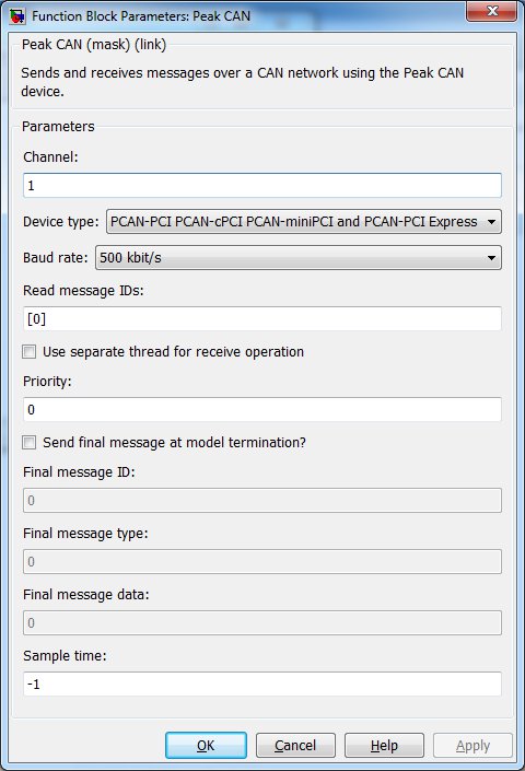
Channel
The channel being used for this connection to the CAN network. Channel numbers are positive integers starting at 1. Consult your Peak CAN device manual for valid channel numbers for your device.
Device type
The type of Peak CAN device being used for this connection. Valid Peak CAN device types are:
Baud rate
The baud rate setting of the Peak CAN device. This should be set to the baud rate of the CAN
network to which the device is connecting. Baud rates supported by the Peak CAN devices are:
                    5 kbit/s, 10 kbit/s, 20 kbit/s, 50 kbit/s, 100 kbit/s, 125 kbit/s, 250 kbit/s, 500 kbit/s,
                    and 1 Mbit/s
.
Read message IDs
A vector of uin32 message IDs to be read. The Peak CAN block receives messages on the
CAN network and will output messages with the IDs specified in this parameter. The order of IDs
specified in this parameter determines the order of the block output vectors type,
length, and data. If this parameter is set to an empty vector
[] then the Peak CAN block will remove the outputs since there will be no messages
received by this block.
Use separate thread for receive operation
When selected, this option forces the Peak CAN block to create a separate thread for performing message read operations. When this option is not selected, reads are done directly by the block. Typically, read operations can be done without a separate thread so this option is not selected by default. If there are many messages being read from the CAN bus, the read operations may take longer and in some cases this may not be ideal for high-speed models (faster than 1kHz); in this case, using a separate thread for read operations may improve performance.
Send final message at model termination?
This option can be activated to send a final message over the CAN network before closing the device at model termination. If this option is not selected, the device will be closed at model termination and no final message will be sent.
Priority
The priority of the thread used for read operations (if selected). In general, a value of 0 indicates the lowest priority and higher values indicate a higher priority. The number of priority levels available depends on the type of QUARC target for which code is being generated.
Final message ID
This parameter is enabled when the Send final message at model termination option is selected.
This parameter is a uint32 value specifies the message ID used for the final message.
Final message type
This parameter is enabled when the Send final message at model termination option is selected.
This parameter is a uint8 value that specifies the message type used for the final message (see the description for the
type input port for valid message types).
Final message data
This parameter is enabled when the Send final message at model termination option is selected.
This parameter is a uint8 vector (of length 1-8) that specifies the message data used for the final message.
Sample time
The sample time of the block. A sample time of 0 indicates that the block will be treated as a continuous time block. A positive sample time indicates that the block is a discrete time block with the given sample time.
A sample time of -1 indicates that the block inherits its sample time. Since this is a source block, only inherent the sample time when it is placed in a conditionally executed subsystem, like a Triggered or Enabled Subsystem, or in a referenced model.
To use the fundamental sampling time of the model, set the sample time to qc_get_step_size, which is a QUARC function that returns the fundamental sampling time of the model.
Targets
|
Target Name |
Compatible* |
Model Referencing |
Comments |
|---|---|---|---|
|
Yes |
Yes |
||
|
Yes |
Yes |
||
|
Yes |
Yes |
||
|
Yes |
Yes |
||
|
Yes |
Yes |
||
|
Yes |
Yes |
||
|
Yes |
Yes |
||
|
Yes |
Yes |
||
|
Yes |
Yes |
||
|
Yes |
Yes |
||
|
No |
No |
Not supported. |
|
|
Yes |
Yes |
||
|
No |
No |
Not supported. |
|
|
No |
No |
Not supported. |
|
|
Rapid Simulation (RSIM) Target |
No |
No |
Not supported. |
|
S-Function Target |
No |
N/A |
Old technology. Use model referencing instead. |
|
Normal simulation |
No |
No |
Not supported. |
Copyright ©2026 Quanser Inc. This page was generated 2026-05-13. Submit feedback to Quanser about this page.
Link to this page.