
PGR Grab Image
Grabs images from the specified Point Grey Research (FLIR) camera.
Library
QUARC Targets/Devices/Third-Party/Point Grey Research/Cameras MATLAB Command Line Click to copy the following command line to the clipboard. Then paste it in the MATLAB Command Window: qc_open_library('quarc_library/Devices/Third-Party/Point Grey Research/Cameras')
Description
The PGR Grab Image block acquires images from a Point Grey Research (PGR) camera (currently available as an FLIR camera) and outputs the image as a matrix of pixel data. The block allows the user to select from various video modes and frame rates, including custom image sizes. All video modes and frame rates may not be possible for the selected camera, and the PGR Grab Image block will attempt to detect if an invalid selection is made. Refer to the camera's specific technical reference document for further information on supported video modes and frame rates.
The PGR Grab Image block spawns a separate thread to grab the images from the camera. The priority of the thread is specified using the Priority parameter of the block. Since a separate thread is generated to read the images from the camera, the PGR Grab Image block can be run at most any sampling rate without having to account for communication delays.
The PGR Grab Image uses a flag output signal to indicate when a new image has arrived and the image data is updated. If the flag signal is 0 there is no new image data and the previous image data remains available at the output. If the flag signal is 1 there is new image data available.
Installation Requirements
 In order to use the PGR Grab Image block, the PGR FlyCapture software must be installed. The software should be included with the camera, or downloaded
from the Point Grey Research website. The recommended version is FlyCapture v2.13. It is recommended that the FlyCapture software be installed
and tested using the FlyCap2 application to ensure that the software is installed correctly and can communicate properly with the camera. A
In order to use the PGR Grab Image block, the PGR FlyCapture software must be installed. The software should be included with the camera, or downloaded
from the Point Grey Research website. The recommended version is FlyCapture v2.13. It is recommended that the FlyCapture software be installed
and tested using the FlyCap2 application to ensure that the software is installed correctly and can communicate properly with the camera. A Complete
installation is recommended, and at minimum the Runtime Libraries and Executables components must be installed for the PGR Grab Image block to work.
The PGR FlyCapture binaries directory must be added to the system Path environment variable. For example, if installed under C:\Program Files\Point Grey Research,
the following should be added to the system's Path environment variable: C:\Program Files\Point Grey Research\FlyCapture2\bin (or
C:\Program Files\Point Grey Research\FlyCapture2\bin64 on 64-bit Windows). Note that if MATLAB
is open when adding the PGR directory to the Path environment variable, MATLAB will need to be closed and reopened.
Input Ports
This block has no input ports.
Output Ports
image
A matrix of type uint8 containing the latest image data acquired from the PGR camera. The image matrix corresponds to the pixel data for the acquired image,
and its dimensions depend on the selected camera and video mode. PGR image data is supplied in row major order, meaning image pixel data are stored row by row instead
of column by column. For a color image mode (eg. RGB), each pixel is described by three bytes (uint8 values).
For example, a 640x480 RGB image is output as a 3x640x480 matrix. For a grayscale image mode, each pixel requires only one byte to describe the luminosity of that pixel;
a 640x480 Greyscale image is output as a 640x480 matrix.
| Color images represent each pixel as red, green and blue (RGB) values, in that order. Currently, the only exception is the FireFlyMV camera in the custom video mode, which uses blue, green, red (BGR) ordering. Note that in the normal video modes, the FireFlyMV camera uses RGB ordering. |
flag
A scalar output indicating whether new image data is available. If the output is 1 there is new image data, otherwise the image output has not been updated with new data.
Parameters and Dialog Box
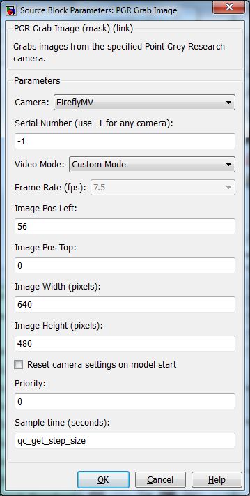
Camera
Determines the camera model to be used. Only the cameras in the list are supported.
Serial Number
The serial number may be used to identify a particular camera, so that multiple cameras may be connected at the same time. The serial number is usually printed on the label on the back of the camera. It may also be determined using the Point Grey FlyCap2 software. For example:
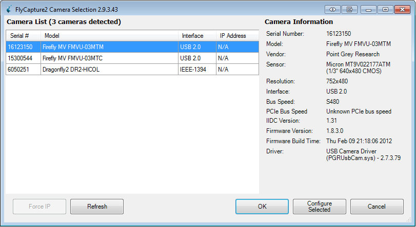
To use the first camera available, enter -1 as the serial number. This is the default value.
Video Mode
This parameter describes the size and type of image that is acquired by the camera. Valid modes include: 640x480 RGB, 640x480 Greyscale, 800x600 RGB, 800x600 Greyscale, 1024x768 RGB, 1024x768 Greyscale, and custom image mode. Cameras may not support all modes. For example, the Flea3 USB 3 color camera only supports custom image mode.
| Note that in custom image mode certain cameras represent color pixel information as RGB (such as Dragonfly2 and Flea3) and other cameras represent color pixel information as BGR (such as FireflyMV). If custom image mode is selected, the Dragonfly2 HI-COL camera will use custom image mode 1 and the FireflyMV and FireflyMV Mono cameras will use custom image mode 0 (see PGR camera documentation for further details). |
All grayscale image modes are represented as 8 bpp (bits-per-pixel) grayscale values.
Frame Rate (fps)
The frame rate in frames-per-second (fps) that the camera will attempt to maintain while grabbing images. The frame rate options include (in fps): 7.5, 15, 30, and 60. Note that certain cameras cannot achieve the exact frame rate desired. Refer to the PGR documentation for more information on the supported frame rates.
This parameter is disabled when custom image mode is selected. In custom image mode, the framerate is determined by the size of the custom image and the camera will attempt to maximize the frame rate. Often, faster frame rates can be achieved with custom image modes than with the standard image modes. The flag output signal can be used to determine the actual frame rate achieved by the camera.
The table below outlines the valid frame rates for each camera and video mode. Note that a custom image video mode will produce images at the fastest possible framerate depending on the size of the custom image. The Flea3 camera is not in the table because it only supports the custom image video mode.
|
Camera |
640x480 RGB |
640x480 Greyscale |
800x600 RGB |
800x600 Greyscale |
1024x768 RGB |
1024x768 Greyscale |
|---|---|---|---|---|---|---|
|
Dragonfly2 HI-COL |
7.5, 15, 30 |
7.5, 15, 30 |
7.5, 15 |
7.5, 15, 30 |
7.5 |
7.5, 15, 30 |
|
FireflyMV |
7.5, 15, 30, 60 |
N/A |
N/A |
N/A |
N/A |
N/A |
|
FireflyMV Mono |
N/A |
7.5, 15, 30, 60 |
N/A |
N/A |
N/A |
N/A |
Image Pos Left
A non-negative scalar integer that is used only for custom image modes. This value is the starting position from the left (in pixels) of the custom image. Note that an arbitrary position may not be supported. For example, the position may need to be a multiple of 16 for some cameras, such as the Flea3.
Image Pos Top
A non-negative scalar integer that is used only for custom image modes. This value is the starting position from the top (in pixels) of the custom image. Note that an arbitrary position may not be supported. For example, the position may need to be a multiple of 16 for some cameras.
Image Width (pixels)
A positive scalar integer that is used only for custom image modes. This value is the image width (in pixels) of the custom image. Note that an arbitrary width may not be supported. For example, the width may need to be a multiple of 16 for some cameras, such as the Flea3.
Image Height (pixels)
A positive scalar integer that is used only for custom image modes. This value is the image height (in pixels) of the custom image. Note that an arbitrary height may not be supported. For example, the height may need to be a multiple of 16 for some cameras.
Reset camera settings on model start
If checked, resets the camera to its factory settings when the model is started. Leave this option unchecked if you do not want to reset the camera settings; this might be useful if you use the Point Grey Research FlyCap software to adjust camera parameters such as brightness, color/gamma saturation, shutter speeds, etc. before running your model.
Priority
The priority of the thread. In general, a value of 0 indicates the lowest priority and higher values indicate a higher priority. The number of priority levels available depends on the type of QUARC target for which code is being generated.
Sample Time
The sample time of the block. A sample time of 0 indicates that the block will be treated as a continuous time block. A positive sample time indicates that the block is a discrete time block with the given sample time.
A sample time of -1 indicates that the block inherits its sample time. Since this is a source block, only inherent the sample time when it is placed in a conditionally executed subsystem, like a Triggered Subsystem, Enabled Subsystem, Function Call Subsystem or in a referenced model.
To use the fundamental sampling time of the model, set the sample time to qc_get_step_size, which is a QUARC function that returns the fundamental sampling time of the model.
The default sample time is set to qc_get_step_size.
Targets
|
Target Name |
Compatible* |
Model Referencing |
Comments |
|---|---|---|---|
|
Yes |
No |
||
|
Yes |
No |
||
|
No |
No |
||
|
No |
No |
||
|
No |
No |
||
|
No |
No |
||
|
No |
No |
||
|
No |
No |
||
|
No |
No |
||
|
No |
No |
||
|
No |
No |
||
|
No |
No |
||
|
No |
No |
||
|
No |
No |
Last fully supported in QUARC 2018. |
|
|
Rapid Simulation (RSIM) Target |
No |
No |
|
|
S-Function Target |
No |
N/A |
Old technology. Use model referencing instead. |
|
Normal simulation |
No |
No |
See Also
Copyright ©2026 Quanser Inc. This page was generated 2026-05-13. Submit feedback to Quanser about this page.
Link to this page.
