
Phantom
Sends forces and torques in Cartesian or joint space to the Sensable Phantom (currently available as 3D System Geomagic Touch) device, and gets the encoder values, position, and joint angles of the robot.

Library
QUARC Targets/Devices/Third-Party/SensAble/Phantom MATLAB Command Line Click to copy the following command line to the clipboard. Then paste it in the MATLAB Command Window: qc_open_library('quarc_library/Devices/Third-Party/SensAble/Phantom')
Description

The Phantom block can be used to control the family of Phantom haptic devices. All these devices have 6 DoF outputs (encoders) to read, and 3 or 6-DOF inputs (actuators) to control. The Phantom block can send commands in two different work spaces to the Phantom device: Cartesian Space and Joint Space. When working in Cartesian mode, block sends the Cartesian forces to the robot, and if the device is 6-DOF, the row, pitch, and yaw commands are sent to the device gimbal. In Joint level mode, the troques are sent to the actuators of the device seperately: 3 values for the arm joints and if the device is 6-DOF, 3 values for the gimbal joints.
Also, depending on the user's choice, the block can output the encoder values, position of the device arm, or joint and gimbal angles of the device. Moreover, the values associated with buttons and possible avaiable 7-DOF on the device (thumb-pad or scissors) are read through this block.
Please be advised that meter is the unit for position and radian for angle.
Installation Requirements
 In order to use the Phantom block, the OpenHaptics Toolkit version 3.4 or later must be installed. Depending on the device being used,
the appropriate device driver must also be installed. For devices that use the Ethernet or USB interface, the Touch Device Driver
v2016.10.13 or later must be installed. For devices that use the FireWire (IEEE-1394a) or parallel port interface, the Phantom Device Driver
v5.1.7 or later must be installed. Note that OpenHaptics and device drivers versions must be compliant with each other. Refer to 3D
Systems website for the proper versions to be installed.
Depending on the device being used, please run "PHANTOM Test" program from the "Phantom Device Drivers" or "Geomagic Touch Setup" and "Geomagic Touch Diagnostic" from "Geomagic Touch Device Drivers" to calibrate the device for better performance.
Input Ports
force
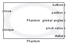
A vector with 3 elements containing the force command in Cartesian space to the arm of the device. This input is active in Cartesian input mode. The units are N.
torque
In 6-DOF devices this 3-elements vector contains the torque command in cartesian space to the device gimbal. This input is active in Cartesian input mode. The units are mN-m.
joint torque
A vector with 3 elements containing the torque commands to the arm joints of the device. This input is active in Joint space input mode. The units are mN-m.
gimbal torque
In 6-DOF devices this 3-elements vector contains the torque commands to the joints of device gimbal. This input is active in joint space input mode. The units are mN-m.
Output Ports
buttons
A scalar value representing the status of the buttons on the device.
encoder values
This output is active when working in "Encoder" output mode, and is a vector with 6 elements representing the encoder values of the 6 joints of the device (3 joints on arm and 3 joints on the gimbal).
position
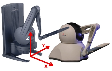
This output is active when working in "Position" output mode, and is a vector with 3 elements representing the Cartesian position of the tip of device arm. The units are mm. The order of the elements is X, Y, Z where the X-axis is positive toward the user (when facing the device), the Y-axis is positive to the right and the Z-axis is positive upward.
joint angles
This output is active when working in "Joint angles" output mode, and is a vector with 3 elements representing the joint angles of the device base, shoulder and elbow joints respectively. The units are radians.
gimbal angles
This output is active when working in "Position" or "Joint angles" output modes, and is a vector with 3 elements representing the joint angles of the device gimbal. The units are radians. The order of the elemnts is yaw, pitch and roll.
pinch value
In devices with the 7-DOF option which is a thumb-pad or scissors, this scalar output represents the pinch value of the thumb-pad or scissors. It is a normalized encoder value.
status
This scalar output represents the status of read and write operations of the device. This signal outputs 0 when working normally, and the error code in case of any problems in calling the API functions.
Parameters and Dialog Box

Device Name
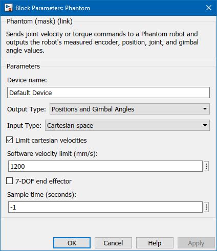
The name assigned to the device. The device has to be configured with Phantom Configuration or Touch Setup program with the same name (e.g., "Default Device"), so the model will access the right device.
Output Type
Allows the user to select the output type from three options: Encoder Values, Position and Gimbal Angles, and Joint and Gimbal Angles. Based on this selection the type of the outputs of the block change.
Input Type
Allows the user to select the input type from two options: Cartesian Space and Joint Space. Based on this selection the type of the inputs of the block change.
Limit Cartesian velocity and Software velocity limit
This option can be activated to limit the cartesian velocity of the device arm for safty features. When Limit Cartesian velocity option is checked, user can limit the velocity to the value in Software velocity limit field. The units of the velocity are mm/s.
7-DOF end effector
When the 7-DOF end effector is available on the device (thumb-pad or scissors), checking this checkbox enables the user to read the pinch value from the end efector as a seperate output signal from the block.
Sample time
The sample time of the block. A sample time of 0 indicates that the block will be treated as a continuous time block. A positive sample time indicates that the block is a discrete time block with the given sample time.
A sample time of -1 indicates that the block inherits its sample time. Since this is a source block, only inherent the sample time when it is placed in a conditionally executed subsystem, like a Triggered or Enabled Subsystem, or in a referenced model.
To use the fundamental sampling time of the model, set the sample time to qc_get_step_size, which is a QUARC function that returns the fundamental sampling time of the model.
Targets
|
Target Name |
Compatible* |
Model Referencing |
Comments |
|---|---|---|---|
|
Yes |
Yes |
||
|
Yes |
Yes |
||
|
No |
No |
||
|
No |
No |
||
|
No |
No |
||
|
No |
No |
||
|
No |
No |
||
|
No |
No |
||
|
No |
No |
||
|
No |
No |
||
|
No |
No |
||
|
No |
No |
||
|
No |
No |
||
|
No |
No |
Last fully supported in QUARC 2018. |
|
|
Rapid Simulation (RSIM) Target |
No |
No |
|
|
S-Function Target |
No |
N/A |
Old technology. Use model referencing instead. |
|
Normal simulation |
No |
No |
See Also

Copyright ©2025 Quanser Inc. This page was generated 2025-11-01. Submit feedback to Quanser about this page.
Link to this page.