
Quanser QBot 2e
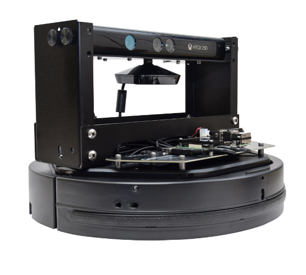
The Quanser QBot 2e is an Unmanned Ground Vehicle (UGV) built and sold by Quanser Inc. The Quanser QBot 2e is based around a Raspberry Pi 3 B+, which has a quad-core 1.4 GHz ARM Cortex-A53 processor with 1 GB RAM running Raspbian. The QUARC Target associated with the Quanser QBot 2e is the QUARC Linux Raspberry Pi 3 Target. The Quanser QBot 2e HIL card may only be used with QUARC when this target is selected. The following characteristics are of particular interest when using the Quanser QBot 2e with QUARC:
* Communications channels are accessed through the Stream API blocks, see Serial protocol,
SPI protocol and I2C protocol.
The Quanser QBot 2e also supports specialized quantities such as the following:
The QUARC driver name for this card is qbot2e.
To select the Quanser QBot 2e HIL board, select the QUARC qbot2e board type from the drop-down list on the Main tab of the HIL Initialize block.
| Note that the QUARC Linux Raspberry Pi 3 Target must be selected to use the Quanser QBot 2e board. |
Communications
The communications ports provided on the Quanser QBot 2e board can be utilized through the QUARC Communications blockset and the Quanser Stream API (see QUARC Communications Protocols).
For SPI communications, a sample URI for communications would be:
spi://localhost:0?baud='1000000',phase='off',lsb='off',frame='0'
where the frame option selects the SPI CE line to frame the SPI bus transaction (0 or 1). Note that
the SPI port must be enabled using the raspi-config utility for SPI communications to be used. Once the SPI port is
enabled, the corresponding digital I/O (pins 19, 21, 23, 24 and 26) will no longer be available as digital I/O.
SPI can also be enabled via the file by setting spi=on in the
Device Tree Overlay parameters. For example:
dtparam=spi=on
After changing , reboot the Raspberry Pi for the changes to take effect.
For I2C communications, a sample URI for communications would be:
i2c://localhost:0?baud='400000',address=0x69
where the address option specifies the I2C slave address. Note that
the I2C port must be enabled using the raspi-config utility for I2C communications to be used. Once the I2C port is
enabled, the corresponding digital I/O (pins 3 and 5) will no longer be available as digital I/O.
To set the baud rate for the I2C, the file must be edited and the Raspbery Pi rebooted. For example, to enable I2C and set the I2C baud rate to 400000 baud, change the Device Tree Overlay parameters to:
dtparam=i2c_arm=on,i2c_arm_baudrate=400000
After changing , reboot the Raspberry Pi for the changes to take effect.
For serial communications, a sample URI for communications would be:
serial://localhost:1?baud='115200',word='8',parity='none',stop='1'
Configuring the Quanser QBot 2e to support serial communications is a bit more involved. First, use the raspi-config
utility to disable the serial port use by the kernel console. Then edit the so
that:
enable_uart=1
Also add the line:
dtoverlay=pi3-disable-bt
in order to disable bluetooth, which makes use of the UART otherwise (see Pi Zero W WiFi interference with TTY). Alternatively, to maintain bluetooth and use the UART, use the lines:
dtoverlay=pi3-miniuart.txt
core_freq=250
Refer to this Raspberry Pi forum topic for details.
After changing , reboot the Raspberry Pi for the changes to take effect. Use the gpio readall command to confirm that the
TxD and RxD pins for the UART are in ALT0 mode. The serial port is /dev/ttyAMA0.
Clocks
There are currently no configuration options for the Quanser QBot 2e clocks.
Analog Inputs
The Quanser QBot 2e supports 6 analog inputs. Hence, analog input channel numbers range from 0 to 5. The full suite of analog inputs are enumerated in the table below:
|
Channel |
Description |
|---|---|
|
0 |
Battery voltage (typically 16.7V when fully charged) |
|
1 |
Raw voltage from right cliff sensor1 |
|
2 |
Raw voltage from central cliff sensor1 |
|
3 |
Raw voltage from left cliff sensor1 |
|
4 |
Right motor current in Amps. |
|
5 |
Left motor current in Amps. |
1 For the non-linear relationship between the raw voltage from a cliff sensor to actual distance, refer to the Sharp Analog Output Type Distance Measuring Sensor Data Sheet.
Analog Outputs
The Quanser QBot 2e card does not support analog outputs.
Digital Inputs
The Quanser QBot 2e supports 59 digital inputs. The first 28 channels are user-accessible reconfigurable digital I/O lines that may be used as digital inputs. Channels 0 and 1, however, are reserved for a HAT EEPROM I2C interface. A digital I/O line cannot be used as an input and output at the same time. Nor can it be used for communications (SPI, I2C or UART) or PWM at the same time. The full suite of digital inputs are enumerated in the following table:
Since the digital I/O lines may be individually programmed as inputs or
outputs on the Quanser QBot 2e, all channels which will be used for digital inputs
should be configured on the HIL Initialize
block's Digital Inputs tab. Set the Digital input channels field to all
the digital I/O channels that will be used as digital inputs on the board for the current diagram. For example, enter
2:4 to designate channels 2 through 4 as digital inputs. Specify
[2, 4, 5] to indicate that channels 2, 4 and 5 are to be configured
as digital inputs.
|
Channel |
Description |
|---|---|
|
0-27 |
User-accessible bidirectional digital I/O lines. Note that channels 0 and 1 are reserved by the O/S for identifying custom Pi 3 daughterboards and cannot be used. |
|
28 |
Right bumper (0 = not pressed, 1 = pressed) |
|
29 |
Central bumper (0 = not pressed, 1 = pressed) |
|
30 |
Left bumper (0 = not pressed, 1 = pressed) |
|
31 |
Right wheel drop (0 = wheel up, 1 = wheel down) |
|
32 |
Left wheel drop (0 = wheel up, 1 = wheel down) |
|
33 |
Right cliff (0 = no cliff, 1 = cliff detected) |
|
34 |
Central cliff (0 = no cliff, 1 = cliff detected) |
|
35 |
Left cliff (0 = no cliff, 1 = cliff detected) |
|
36 |
Button B0 (0 = not pressed, 1 = pressed) |
|
37 |
Button B1 (0 = not pressed, 1 = pressed) |
|
38 |
Button B2 (0 = not pressed, 1 = pressed) |
|
39 |
Right motor overcurrent (0 = normal operation, 1 = overcurrent detected) |
|
40 |
Left motor overcurrent (0 = normal operation, 1 = overcurrent detected) |
|
41 |
Right dock IR near right sensor (0 = not detected, 1 = detected) |
|
42 |
Right dock IR near center sensor (0 = not detected, 1 = detected) |
|
43 |
Right dock IR near left sensor (0 = not detected, 1 = detected) |
|
44 |
Right dock IR far right sensor (0 = not detected, 1 = detected) |
|
45 |
Right dock IR far center sensor (0 = not detected, 1 = detected) |
|
46 |
Right dock IR far left sensor (0 = not detected, 1 = detected) |
|
47 |
Central dock IR near right sensor (0 = not detected, 1 = detected) |
|
48 |
Central dock IR near center sensor (0 = not detected, 1 = detected) |
|
49 |
Central dock IR near left sensor (0 = not detected, 1 = detected) |
|
50 |
Central dock IR far right sensor (0 = not detected, 1 = detected) |
|
51 |
Central dock IR far center sensor (0 = not detected, 1 = detected) |
|
52 |
Central dock IR far left sensor (0 = not detected, 1 = detected) |
|
53 |
Left dock IR near right sensor (0 = not detected, 1 = detected) |
|
54 |
Left dock IR near center sensor (0 = not detected, 1 = detected) |
|
55 |
Left dock IR near left sensor (0 = not detected, 1 = detected) |
|
56 |
Left dock IR far right sensor (0 = not detected, 1 = detected) |
|
57 |
Left dock IR far center sensor (0 = not detected, 1 = detected) |
|
58 |
Left dock IR far left sensor (0 = not detected, 1 = detected) |
Note that the dock IR signals may oscillate when the IR signal is detected. This oscillation is a function of the way the docking IR signals work.
Digital Outputs
The Quanser QBot 2e supports 36 digital outputs. The first 28 channels are user-accessible reconfigurable digital I/O lines that may be used as digital outputs. Channels 0 and 1, however, are reserved for a HAT EEPROM I2C interface. A digital I/O line cannot be used as an input and output at the same time. Nor can it be used for communications (SPI, I2C or UART) or PWM at the same time.
Since the digital I/O lines may be individually programmed as inputs or outputs
on the Quanser QBot 2e, all the channels which will be used for digital outputs should be configured
on the HIL Initialize block's
Digital Outputs tab. Set the Digital output channels
field to all the bidirectional digital I/O channels that will
be used as digital outputs on the board for the current diagram. For example, enter
2:4 to designate channels 2 through 4 as digital outputs. Specify
[2, 4, 5] to indicate that channels 2, 4 and 5 are to be configured
as digital outputs.
To set the digital output values when the model is loaded or unloaded, set the Initial digital outputs and Final digital outputs to the desired values respectively. If the vectors specified in these fields are shorter than the channel vector, the value of the last element in the vector will be used for the rest of the channels. Hence, a scalar value will apply to all channels specified in the Digital output channels field.
The full suite of digital outputs are enumerated in the following table:
|
Channel |
Description |
|---|---|
|
0-27 |
User-accessible bidirectional digital I/O lines. Note that channels 0 and 1 are reserved by the O/S for identifying custom Pi 3 daughterboards and cannot be used. |
|
28 |
Chassis LED1 red |
|
29 |
Chassis LED1 green |
|
30 |
Chassis LED2 red |
|
31 |
Chassis LED2 green |
|
32 |
Enable 3.3V power |
|
33 |
Enable 5V power |
|
34 |
Enable 12V/5A power1 |
|
35 |
Enable 12V/1.5A power |
1 Disabling the 12V/5A power will power down the Raspbery Pi 3 processor. The chassis will have to be turned off and back on in order to restore power and wireless communications with the Pi 3 target.
Encoder Inputs
The Quanser QBot 2e supports two encoder inputs. The encoder channels are enumerated in the table below:
|
Channel |
Description |
|---|---|
|
0 |
Right wheel |
|
1 |
Left wheel |
In order to set the encoder counters to a particular count, the encoder inputs must
be configured on the HIL Initialize
block's Encoder Inputs tab. Set the Encoder input channels
field to all the encoder channels that will be
used on the board for the current diagram. For example, enter
0:1
to
indicate channels 0 through 1 are used as encoder inputs.
PWM Outputs
The Quanser QBot 2e driver supports up to 2 PWM output channels. Hence, PWM output channels range from 0 to 1. Each PWM channel is completely independent and can have its own duty cycle and frequency.
Before the PWM channels may be used, they must be configured in the file and in the board-specific
options. The file must be edited with root privileges. For example, to use the vi editor,
enter the command:
sudo vi /boot/config.txt
in a terminal window.
The lines which must be added to the file depend on the number of PWM channels desired, and the pins to which they are assigned. The following table documents the lines that must be added to the file for each combination of options:
|
PWM 0 |
PWM 1 |
Line to Add |
|---|---|---|
|
disabled |
disabled |
Do not add any lines |
|
GPIO 12 |
disabled |
|
|
GPIO 18 |
disabled |
|
|
disabled |
GPIO 13 |
|
|
disabled |
GPIO 19 |
|
|
GPIO 12 |
GPIO 13 |
|
|
GPIO 12 |
GPIO 19 |
|
|
GPIO 18 |
GPIO 13 |
|
|
GPIO 18 |
GPIO 19 |
|
| Note that once a GPIO is configured as a PWM channel then it will no longer be recognized as a digital I/O line. |
In order to configure the PWM mode or frequency, or to set the value of the PWM outputs when the model is loaded or unloaded, the PWM
outputs must be configured on the HIL Initialize block's
PWM Outputs tab. Set the PWM output channels field to all the PWM output channels that will be used on the
board for the current diagram. For example, enter 0:1 to indicate channels 0 and 1. Specify 1 to indicate channel 1 alone.
The PWM outputs are generic PWM outputs that are capable of producing the standard analog ESC protocols, namely standard PWM (1000us to 2000us), Oneshot125 (125us to 250us), Oneshot42 (42us to 84us) and Multishot (5us to 25us). They may also be used to drive R/C servos.
The PWM parameters for each of these protocols are tabulated below:
|
Protocol |
PWM Frequency |
Pulse Time Range |
Duty Cycle Range |
|---|---|---|---|
|
Standard PWM |
50 Hz (20ms) |
0.001 to 0.002 seconds (1ms to 2ms) |
0.05 to 0.1 (5% to 10%) |
|
Oneshot125 |
2000 Hz (500us) |
125e-6 to 250e-6 seconds (125us to 250us) |
0.25 to 0.5 (25% to 50%) |
|
Oneshot42 |
11905 Hz (84us) |
42e-6 to 84e-6 seconds (42us to 84us) |
0.25 to 0.5 (25% to 50%) |
|
Multishot |
20000 Hz (50us) |
5e-6 to 25e-6 seconds (5us to 25us) |
0.1 to 0.5 (10% to 50%) |
The PWM outputs are not restricted to these parameter values as they are generic PWM outputs. The maximum output frequency is 50 MHz. The number of bits of resolution decreases with increasing PWM output frequency.
Set the PWM output frequency (a.k.a., pulse rate) in the "Frequencies in Hz or duty cycle" field. The PWM output mode is typically set to duty cycle mode (0) or time mode (4) when driving ESCs or R/C servos. Set the Initial PWM outputs and Final PWM outputs fields to the desired initial and final output values respectively. The interpretation of these output values depends on the PWM mode selected. If the vectors specified in these fields are shorter than the channel vector, the value of the last element in the vector will be used for the rest of the channels. Hence, a scalar value will apply to all channels specified in the PWM output channels field.
Other Inputs
The Quanser QBot 2e supports eight other input channels. The other input channels are defined as follows:
|
Other Input Channel |
Description |
Units |
|---|---|---|
|
1002 |
Angle in Z-axis |
(rad) |
|
3000 |
Gyroscope in X |
(rad/s) |
|
3001 |
Gyroscope in Y |
(rad/s) |
|
3002 |
Gyroscope in Z |
(rad/s) |
|
11000 |
Right wheel PWM |
(%) |
|
11001 |
Left wheel PWM |
(%) |
|
12000 |
Timestamp |
(s) |
|
16000 |
Charger state |
1 |
1 The charger state takes on discrete values depending on whether the docking station is being used and whether the battery is fully charged. The following table shows the charger state values:
|
State |
Description |
|---|---|
|
0 |
Discharging battery |
|
2 |
Battery charged at docking station |
|
6 |
Battery charging at docking station |
|
18 |
Battery charged using adapter |
|
22 |
Battery charging using adapter |
Channel numbers for Other Input or Output channels use predefined ranges for each type of measurement to ensure consistency between data acquisition devices. Refer to QUARC Other Channels for a list of the Other Input or Output channel number ranges defined for any HIL Data Acquisition Card and their SI units.
Other Outputs
The Quanser QBot 2e supports four other output channels, allowing the wheel velocities to be controlled and sounds to be generated. Refer to the table below for a list of the channels:
|
Channel |
Description |
Units |
|---|---|---|
|
2000 |
Right wheel velocity |
(m/s) |
|
2001 |
Left wheel velocity |
(m/s) |
|
14000 |
Pitch of custom sound |
(Hz) |
|
16000 |
Predefined sound |
(0-6) |
Channel numbers for Other Input or Output channels use predefined ranges for each type of measurement to ensure consistency between data acquisition devices. Refer to QUARC Other Channels for a list of the Other Input or Output channel number ranges defined for any HIL Data Acquisition Card and their SI units.
Interrupts
The Quanser QBot 2e card, or its driver, does not support any interrupt sources.
Watchdog
The Quanser QBot 2e card does not support a watchdog timer.
Board-Specific Options
The Quanser QBot 2e has a number of board-specific options to control specialized functionality of the board. These options configure the PWM.
pwm0_en
This option is a boolean value that enable or disables PWM 0. If PWM 0 is disabled then the PWM pin may be used as a regular digital I/O. Valid values are 0, 1, false, true, off, on, no or yes.
pwm1_en
This option is a boolean value that enable or disables PWM 1. If PWM 1 is disabled then the PWM pin may be used as a regular digital I/O. Valid values are 0, 1, false, true, off, on, no or yes.
pwm0_pin
This option determines which pin will be used for PWM 0. Valid values are 12 or 18 corresponding to GPIO 12 or GPIO 18 respectively.
| Note that once a GPIO is configured as a PWM channel then it will no longer be recognized as a digital I/O line. |
pwm1_pin
This option determines which pin will be used for PWM 1. Valid values are 13 or 19 corresponding to GPIO 13 or GPIO 19 respectively.
| Note that once a GPIO is configured as a PWM channel then it will no longer be recognized as a digital I/O line. |
Properties
The Quanser QBot 2e driver currently supports the following read-only properties:
|
Property |
Type |
Description |
|---|---|---|
|
PROPERTY_INTEGER_MAJOR_VERSION |
Integer |
Major version number of the hardware |
|
PROPERTY_INTEGER_MINOR_VERSION |
Integer |
Minor version number of the hardware |
|
PROPERTY_INTEGER_BUILD |
Integer |
Build number of the hardware (currently always zero) |
|
PROPERTY_INTEGER_REVISION |
Integer |
Revision or patch number of the hardware |
|
PROPERTY_INTEGER_FIRMWARE_MAJOR_VERSION |
Integer |
Major version number of the firmware |
|
PROPERTY_INTEGER_FIRMWARE_MINOR_VERSION |
Integer |
Minor version number of the firmware |
|
PROPERTY_INTEGER_FIRMWARE_BUILD |
Integer |
Build number of the firmware (currently always zero) |
|
PROPERTY_INTEGER_HARDWARE_VERSION |
Integer |
Revision or patch number of the firmware |
|
PROPERTY_INTEGER_KOBUKI_UDID0 |
Integer |
Unique identifier 0 |
|
PROPERTY_INTEGER_KOBUKI_UDID1 |
Integer |
Unique identifier 1 |
|
PROPERTY_INTEGER_KOBUKI_UDID2 |
Integer |
Unique identifier 2 |
The following properties may be both read and written:
|
Property |
Type |
Description |
|---|---|---|
|
PROPERTY_DOUBLE_KOBUKI_P_GAIN |
Double |
Proportional gain for the onboard controller. The factory value is 100. |
|
PROPERTY_DOUBLE_KOBUKI_I_GAIN |
Double |
Integral gain for the onboard controller. The factory value is 0.1. |
|
PROPERTY_DOUBLE_KOBUKI_D_GAIN |
Double |
Derivative gain for the onboard controller. The factory value is 2. |
Connectors
The Quanser QBot 2e board has one connector for expansion I/O. The pinouts for this connector are listed below. Note that all pins are 3.3V and are not 5V tolerant unless marked otherwise. Exceeding these voltages may damage the board!
Raspberry Pi GPIO Connector
GPIO 21 ↔ | 40 | 39 | ― Ground |
GPIO 20 ↔ | 38 | 37 | ↔ GPIO 26 |
GPIO 16 ↔ | 36 | 35 | ↔ GPIO 19 / → PWM 1 |
Ground ― | 34 | 33 | ↔ GPIO 13 / → PWM 1 |
PWM 0 ← / GPIO 12 ↔ | 32 | 31 | ↔ GPIO 6 |
Ground ― | 30 | 29 | ↔ GPIO 5 |
ID SC / GPIO 1 ↔ | 28 | 27 | ↔ GPIO 0 / ID SD |
SPI CE1 ← / GPIO 7 ↔ | 26 | 25 | ― Ground |
SPI CE0 ← / GPIO 8 ↔ | 24 | 23 | ↔ GPIO 11 / → SPI SCLK |
GPIO 25 ↔ | 22 | 21 | ↔ GPIO 9 / ← SPI MISO |
Ground ― | 20 | 19 | ↔ GPIO 10 / → SPI MOSI |
GPIO 24 ↔ | 18 | 17 | ― 3.3V |
GPIO 23 ↔ | 16 | 15 | ↔ GPIO 22 |
Ground ― | 14 | 13 | ↔ GPIO 27 |
PWM 0 ← / GPIO 18 ↔ | 12 | 11 | ↔ GPIO 17 |
UART RXD → / GPIO 15 ↔ | 10 | 9 | ― Ground |
UART TXD ← / GPIO 14 ↔ | 8 | 7 | ↔ GPIO 4 |
Ground ― | 6 | 5 | ↔ GPIO 3 / I2C SCL |
5V ― | 4 | 3 | ↔ GPIO 2 / I2C SDA |
5V ― | 2 | 1 | ― 3.3V |
Legend
→▯← | = | input |
←▯→ | = | output |
↔▯↔ | = | bidirectional I/O |
= | 3.3V signal | |
= | power | |
= | ground |
Targets
|
Target |
Supported |
Comments |
|---|---|---|
|
No |
Not supported. |
|
|
No |
Not supported. |
|
|
No |
Not supported. |
|
|
No |
Not supported. |
|
|
No |
Not supported. |
|
|
No |
Not supported. |
|
|
No |
Not supported. |
|
|
No |
Not supported. |
|
|
No |
Not supported. |
|
|
No |
Not supported. |
|
|
No |
Not supported. |
|
|
No |
Not supported. |
|
|
No |
Not supported. |
|
|
No |
Not supported. |
|
|
No |
Not supported. |
|
|
Rapid Simulation (RSIM) Target |
Yes |
Supported with no communication to the hardware. |
|
Normal simulation |
Yes |
Supported with no communication to the hardware. |
See Also
Copyright ©2026 Quanser Inc. This page was generated 2026-05-13. Submit feedback to Quanser about this page.
Link to this page.
