MATLAB Command Line
Click to copy the following command line to the clipboard. Then paste it in the MATLAB Command Window:
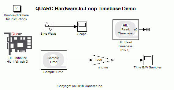
quarc_hil_timebase_demoQUARC Hardware-In-Loop Timebase Demo
This example demonstrates how to use a HIL Timebase block from the QUARC Targets library to improve timing performance of a model. With a HIL Timebase block in the model, the Hardware-In-Loop timer would be used as the timebase as opposed to the system timer. This family of blocks should also be used when the model is to run at a sampling frequency above 1 KHz since the system timer does not provide accurate timing for such high frequencies and the model would miss sampling instants. For details of this family of blocks, please refer to the QUARC Generic HIL Blocks - Timebases reference section in the QUARC documentation.

This example uses the "Sample Time" block from the QUARC Targets library to measure the actual time between each sampling instant using an independent high-resolution time source. For more details, please refer to the Sample Time block reference page.
This example consists of two demonstrations. First, the timing performance of the model without the HIL Timebase block is compared to the case where it is included. Next, a sampling frequency of 10 KHz is chosen for the model and we showcase the fact that the system timer cannot be used as the timebase while the hardware timebase works fine for such high sampling frequencies.
System Requirements
This demonstration requires hardware supported by the HIL blockset, such as the Q2-USB or Q8-USB hardware-in-the-loop card.
Configuring the Demonstration
To set up the demonstration for your data acquisition card, double-click on the HIL Initialize block and select the correct board type from the Board type combo box. If you have more than one board of the same type in your computer, change the Board number field to the board you wish to use. Boards are numbered from 0 such that board 0 is the first board recognized by the HIL blockset.
Demonstration 1 - Timing Performance Improvement
To set up this demonstration, open the Configuration Parameters Dialog by pressing Ctrl+E or
selecting the button on the MODELING tab.
In the Solver pane, make sure that the Fixed-step size (fundamental sample time)
parameter is set to 0.001 which corresponds to 1 KHz as the model sampling frequency.
Building, deploying and starting the model
Refer to One Step Process in QUARC Basic Procedures to build, deploy and start the model.
Running the model
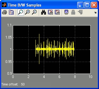
Double-click on the "Time B/W Samples" Scope block to display the time between samples in ms.
The "Time B/W Samples" Scope will trace a signal similar to the following figure (you might need to Autoscale the scope to display the signal).
Stopping the model
Refer to One Step Process in QUARC Basic Procedures to stop the model.
Once the model is stopped, delete the "HIL Read Timebase" block from the diagram. Repeat the procedure mentioned above to build, connect to and start the model.
By deleting the "HIL Read Timebase" block, the model gets configured to use the system timer as its timebase. The "Time B/W Samples" Scope traces a signal similar to the following figure (you might have to Autoscale the scope to view the signal).
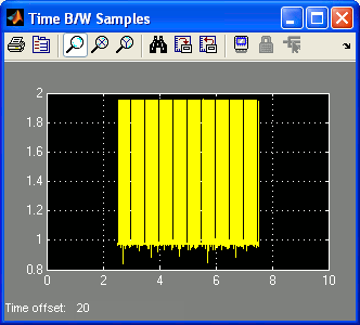
Comparing the figures, you can observe that the deviation of the time between the samples in the model with the "HIL Read Timebase" block is much less than the case where this block is deleted. Notice that in ideal case, the Scopes should have traced a constant signal with a value of 1 ms. Nevertheless, the HIL Timebase block reduces the deviation in the timing. Less deviation in the time between the samples corresponds to less timing jitter, hence improved performance.
Click on the button or select from the menu of the diagram to stop the model. The item of the menu may also be used.
Add the deleted "HIL Read Timebase" block to the model using the Simulink Library Browser. This block resides in the QUARC Targets/Data Acquisition/Generic/Timebases category. Once the block is added, save the model.
Demonstration 2 - Running the Model at 10 KHz
To set up this demonstration, open the Configuration Parameters Dialog by pressing Ctrl+E or
selecting the button on the MODELING tab.
In the Solver pane, change the Fixed-step size (fundamental sample time)
parameter to 0.0001 which corresponds to 10 KHz as the model sampling frequency.
Building, deploying and starting the model
Refer to One Step Process in QUARC Basic Procedures to build, deploy and start the model.
Running the model
Double-click on the "Time B/W Samples" Scope block to display the time between samples in ms.
The "Time B/W Samples" Scope will trace a signal similar to the following figure (you might need to Autoscale the scope to display the signal).
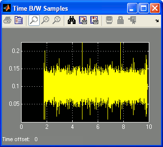
Notice that there is more deviation when the sampling frequency is 10 KHz. This is because the hardware timer has a specific accuracy measure, but as the sampling frequency is increased, models demand more accuracy. Therefore, you notice more deviation in the case of model running at 10 KHz as opposed to the one running at 1 KHz.
Stopping the model
Refer to One Step Process in QUARC Basic Procedures to stop the model.
Now, delete the "HIL Read Timebase" block from the diagram and repeat the above mentioned procedure to build, connect to and start the model.
The model is now configured to run at 10 KHz using the system timer. Since this timing period is too fast for the system timer, an error is displayed which is similar to the following figure.
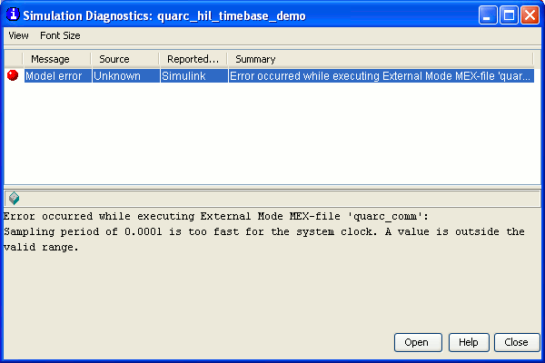
This example demonstrates the need for a Hardware-In-Loop card when trying to run models at frequencies above the 1 KHz mark.
Running the example on a different target
To run the example on a different target, refer to the instructions on the Running QUARC Examples on Remote Targets page.
Be sure to configure the HIL Initialize block's board type for the board on the new target, as per the instructions in the Configuring the Demonstration section above.
Copyright ©2025 Quanser Inc. This page was generated 2025-11-01. Submit feedback to Quanser about this page.
Link to this page.