MATLAB Command Line
Click to copy the following command line to the clipboard. Then paste it in the MATLAB Command Window:
quarc_spi_gyroscope_mixed_types_demoQUARC SPI Gyroscope Mixed Types Demo
This is an example of using an SPI device with QUARC that outputs 16-bit values. It interfaces with a three-axis gyroscope sensor. This example also illustrates how to read mixed data types by using bus objects. Refer to Using Bus Objects with QUARC for more details on bus objects.
System Requirements
This demonstration is run using the QUARC for Windows or QUARC for Win64 target with a Quanser QPID or QPIDe data acquisition card for SPI support. This example may also be run on other SPI-capable QUARC targets, such as the QUARC Linux DuoVero Target on the QBot 2 or QBall 2. No QPID(e) card is required in that case. Note that a software license for the desired target is required.
To run on other QUARC targets supporting SPI, the appropriate HIL board will need to be selected, voltage levels will need to be checked (+3.3V required), and the port and frame option of the URI in the Stream Call block will likely need to be changed. Further details may be found below under the heading Running the example on a different target.
This example also requires an L3G4200D or L3GD20 three-axis digital output gyroscope sensor from STMicroelectronics Inc., wired to SPI port 0 of the target. A convenient peripheral module called the PmodGYRO is provided by Digilient Inc. that uses the L3G4200D digital output gyroscope. This example was tested using this peripheral module.
The connections to make to the J1 connector of the PmodGyro are shown in the table below. See the PmodGYRO Reference Manual and PmodGYRO Schematic for details.
|
Pin |
Name |
Connection |
|---|---|---|
|
1 |
CS |
Connect to digital output 56 (SS) of the QPID(e), or whichever digital output will be used as the "frame" signal. Note that the "frame" option in the URI of the Stream Call block must match this digital output. |
|
2 |
SDA/SDI/SDO |
Connect to master-out slave-in (MOSI) line of SPI port 0 of the QPID(e). |
|
3 |
SDO/SD0 |
Connect to master-in slave-out (MISO) line of SPI port 0 of the QPID(e). |
|
4 |
SCL/SPC |
Connect to the serial clock (SCK) line of SPI port 0 of the QPID(e). |
|
5 |
GND |
Connect to ground (DGND) of the QPID(e). |
|
6 |
VCC |
Connect to a +3.3V supply (be sure to connect the supply's ground to pin 5 or 11). |
Configuring the Demonstration
The frame option of the URI used by the Stream Call block must match the digital output connected to the CS line of the gyroscope. If this pins is connected to a different digital output than digital output 56 (SS), then the value of the frame option will need to be changed to match the digital output used. The baud rate may also be changed, but the other options should be left alone, because they match the SPI phase and polarity to that required by the gyroscope. The gyroscope does not support a baud rate faster than 10 MHz (10e6).
To change the URI of the Stream Call block, double-click on the block to open its configuration dialog, as shown below.
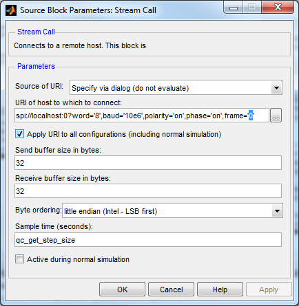
In the URI of host to which to connect field, replace the value of the baud option in the URI with the desired baud rate. If the example is being run on a target other than Windows then the port number and frame option may need to be changed as well. See the SPI Protocol documentation for details on the format of the URI.
Click OK to close the configuration dialog.
Running the Model Using the QUARC Target for Windows
Please note that in order to be able to run this part of the demo, you must have purchased the QUARC Target for Windows as part of your license. In addition you must have satisfied the software and hardware requirements found in the QUARC Installation Guide.
To open the model click on the "Open this model" button found on the top right corner of this page.
Select from the menu of the diagram, or select from the simulation mode combo box on the toolbar.
Select from the menu of the diagram, or press Ctrl+B while the diagram is the active window. A great deal of output will appear in the Diagnostic Viewer about the progress of the build. If you cannot see the Diagnostic Viewer, you can open it by selecting from the menu of the diagram, or clicking on the View Diagnostics hyperlink at the bottom of the diagram. If you have MATLAB R2013b or earlier then the output will appear in the MATLAB Command Window.
If the build is successful, then the line:
*** Created executable quarc_spi_gyroscope_mixed_types_demo.rt-win64
will appear in the Diagnostic Viewer. Finally, QUARC will download the model to the QUARC Target for Windows. The line:
### Model quarc_spi_gyroscope_mixed_types_demo has been downloaded to target 'shmem://quarc-target:1' (55296 bytes)
will appear in the Diagnostic Viewer indicating that the code was successfully downloaded to the QUARC Target. If any errors occur, appropriate error messages will appear in the Diagnostic Viewer.
Double click on the Temperature (°C) block to open its Scope. Also double click on the Rates (deg/s) block to open its Scope.
Click on the button or select from the menu of the diagram to connect to the model.
Start the model by clicking on the button or selecting from the menu of the diagram. The item of the menu may also be used to both connect and start the model in one operation.
A straight line will appear matching the ambient temperature in the Scope as shown below. Breath on the sensor to increase the temperature of the sensor and see the corresponding increase on the Scope. The gyroscope's temperature sensor is only accurate to one degree centigrade and is only updated once per second, so the plot will be a bit crude. Notice that the Scope trace is moving in actual time. In other words, the trace passes the 10 second mark after 10 seconds have passed since in external mode, QUARC runs the model in real-time.
Rotate the gyroscope about its Cartesian axes. The angular velocities in degrees per second will appear in the Scope as shown below. The full scale range of the gyroscope was initialized to 500 deg/s by the model, so it will saturate at ±500 deg/s. The range can be programmed as 250 deg/s or 2000 deg/s as well by changing the way the CTRL_REG4 register is programmed in the Initialize Gyroscope subsystem.
Click on the button or select from the menu of the diagram to stop the model. The item of the menu may also be used.
Running the example on a different target
To run the example on a different target, refer to the instructions on the Running QUARC Examples on Remote Targets page.
The URI of the Stream Call block must also be changed to suit the particular target. Below are sample URIs for different QUARC targets that support SPI:
|
Target |
Port |
Chip Select |
URI |
|---|---|---|---|
|
QUARC Windows Target with QPID(e) |
0 |
SS |
spi://localhost:0?word='8',baud='10e6',polarity='on',phase='on',frame='56' |
|
QUARC Win64 Target with QPID(e) |
0 |
SS |
spi://localhost:0?word='8',baud='10e6',polarity='on',phase='on',frame='56' |
|
QUARC Linux DuoVero Target on QBot 2 |
1 |
CS0 |
spi://localhost:1?word='8',baud='10e6',polarity='on',phase='on',frame='0' |
|
QUARC Linux DuoVero Target on QBall 2 |
1 |
CS0 |
spi://localhost:1?word='8',baud='10e6',polarity='on',phase='on',frame='0' |
When wiring the gyroscope on a different target, use the same wiring diagram but replace the QPIDe with the equivalent I/O on the target platform. The table above shows the SPI port and chip select to use for some sample targets.
Copyright ©2026 Quanser Inc. This page was generated 2026-05-13. Submit feedback to Quanser about this page.
Link to this page.