
Using Bus Objects with QUARC
QUARC supports bus signals for some of its communications blocks in Simulink. Bus signals allow mixed data types to be combined into
a single "bus" signal much like a Mux
MATLAB Command Line
Click to copy the following command line to the clipboard. Then paste it in the MATLAB Command Window:
doc('Mux') combines multiple signals of the same type
into a vector. For example, a bus can contain doubles, integers and boolean values all in the same signal. By feeding a bus signal
to a Stream Write block, the signals in the bus can be sent as one
atomic unit over the communication channel. Byte ordering is performed correctly, even though different data types may be contained
in the bus. In the C language, buses are represented as structures, with the fields in the structure representing the
different signals contained within the bus. Hence, wiring a bus to a Stream Write block is equivalent to sending
a structure over the communication channel. Similarly, a Stream Read block
may be configured to read a structure from the input stream and output it as a bus signal.
Creating a Bus Object
To use bus signals with QUARC, a bus object must first be defined. Bus objects are instances of the Simulink.Bus MATLAB Command Line Click to copy the following command line to the clipboard. Then paste it in the MATLAB Command Window: doc('Simulink.Bus') class. They are easily created using the Simulink Bus Editor. To open the Bus Editor, select the menu on the Simulink diagram. The dialog illustrated below, or one with similar functionality, will open.
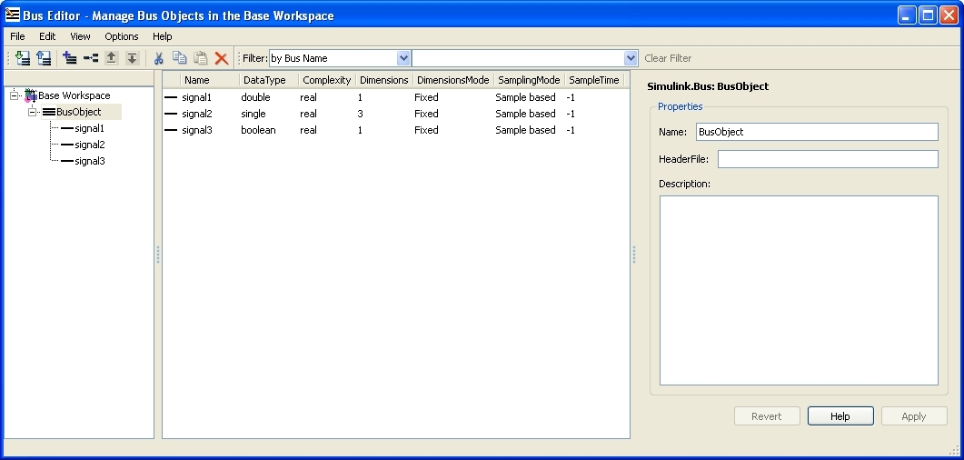
A bus is created using the  button on the toolbar.
The Bus Editor will create the bus object as a variable in the MATLAB workspace. The name of the variable is the same as the name
of the bus object.
button on the toolbar.
The Bus Editor will create the bus object as a variable in the MATLAB workspace. The name of the variable is the same as the name
of the bus object.
Signals are added to the bus using the  button. The properties of each signal can be edited in terms of its name, data type, dimensions, etc. The properties for an element called
 signal1
are depicted below as an example.
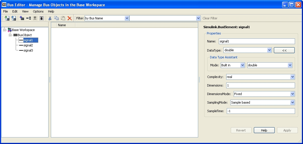
 The names of the signals in the bus object should generally be called
 signal1, signal2, etc. to match the default naming
convention used by Simulink for signals in a bus. If this naming scheme is not followed then warnings will be generated in the MATLAB
command window when the bus object is actually used in the diagram (unless the signals being wired into the bus are named via the
Signal Properties dialog in Simulink).
Saving the Bus Object
Once a bus object has been created using the Bus Editor, it should be saved to a MAT file. When Simulink blocks use bus objects, the
bus objects must be defined in MATLAB's base workspace. Unfortunately, that restriction means that typing the clear command
will clear the bus object variable from the base workspace and the bus object definition will be lost.
| To prevent such a tragic loss of your work, bus objects should be saved to a MAT file. |
To save the bus object to a MAT file, use the save
MATLAB Command Line
Click to copy the following command line to the clipboard. Then paste it in the MATLAB Command Window:
doc('save') command. For example,
if the bus object is called BusObject, then save it to a file called my_bus_object.mat using the command:
save my_bus_object.mat BusObject
Even though this operation saves the bus object, it does not prevent the bus object from being cleared from the MATLAB workspace. The bus object can always be reloaded manually by issuing the command:
load my_bus_object.mat
but doing so would get tedious after a while. A better solution is to have the model load the bus object from the MAT file whenever the bus object is required. This procedure is outlined in the next section.
Loading the Bus Object Automatically
The bus object is generally required whenever the model is updated, code is generated, or the model is being run. Thankfully, there is a way to ensure that the bus object is always available when needed, even if the MATLAB workspace has been cleared.
The InitFcn callback of a model is executed every time the model is updated, code is generated, or the model
is started. Hence, this callback is the ideal place to issue a load command to import the bus object into the MATLAB
workspace.
To edit the InitFcn callback of a model, open the Model Properties dialog using the
menu item of the Simulink diagram. Then click on the Callbacks tab to view the callbacks for the model. This tab
is shown below.
Click on the item to view the contents of the InitFcn callback. From the previous example, if the
bus object is saved in a file called my_bus_object.mat in the MATLAB path, then enter the command:
load my_bus_object.mat
in the edit field for the callback. Alternatively, if the file is saved to the same folder as the model itself, the following command may be used to ensure that the absolute path to the MAT file is used:
load(fullfile(fileparts(get_param(bdroot, 'Filename')), 'my_bus_object.mat'))
The get_param(bdroot, 'Filename') function returns the full path to the Simulink model. Then fileparts is used
to extract the folder containing the Simulink model. Finally the fullfile function is used to form the full path to
the MAT file, which is loaded by the load command.
Click to close the Model Properties dialog and save the changes.
Sending Data Using Bus Objects
Once a bus object has been defined, it may be used to create a bus signal in Simulink. This signal may then be fed to the input of one of the QUARC communications blocks, such as the Stream Write block to send the contents of the bus to the peer.
Bus signals are created using the Bus Creator MATLAB Command Line Click to copy the following command line to the clipboard. Then paste it in the MATLAB Command Window: doc('Bus Creator') block. Drag the block into the model from the Simulink Library Browser. Double-click on the Bus Creator block to open its properties. A dialog similar to the one shown below will appear.
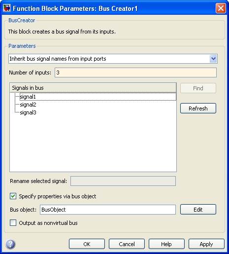
Change the Number of inputs field to the number of inputs that will be combined into a bus signal. In this example, three inputs were selected.
Ensure that the Specify properties via a bus object option is checked. Then type in the name of the bus object created using the procedure outlined in the previous sections in the Bus object field. The button may be used to create the bus object right from the Bus Creator block properties dialog.
| The names of the signals in the bus object should match the names of the signals enumerated in the Signals in bus list. Otherwise Simulink will issues warnings in the MATLAB command window about mismatched signal names. To change the names of signals in your diagram, right-click on a signal line and select the menu item. Then enter the name of the signal in the Signal name field and click to close the Signal Properties dialog. |
Ensure that the Output as nonvirtual bus option is checked. This option forces the output of the Bus Creator block to be a non-virtual bus, which is required by the QUARC blocks that support buses. It also provides better error reporting for tracking down errors with bus signals.
Click to save the settings. Then simply wire the output of the Bus Creator block to the data input of the Stream Write block, or whichever communication block is employed to send the data to the peer.
Receiving Data Using Bus Objects
When receiving data as a bus, the Stream block used requires the name of the bus object in order to define the bus. For example, to use bus signals with the Stream Read block, double-click on the Stream Read block to open its properties dialog, which is depicted below.
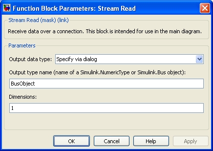
Change the Output data type field to Specify via dialog. Then enter the name
of the bus object defining the bus in the Output type name field. In this example, the name of the
bus object is BusObject. Remember that this field is the name of the variable in the MATLAB workspace that defines
the bus object. The Dimensions field should be set to 1.
| The name entered in the Output type name field must match the name of a variable in the MATLAB workspace. An expression may not be used in place of the variable name. |
Click to close the dialog and save the properties. The Stream Read block will now read the data types defined by the bus object and output the data as a bus signal. The Bus Selector MATLAB Command Line Click to copy the following command line to the clipboard. Then paste it in the MATLAB Command Window: doc('Bus Selector') block may be used to extract the component signals from the bus signal.
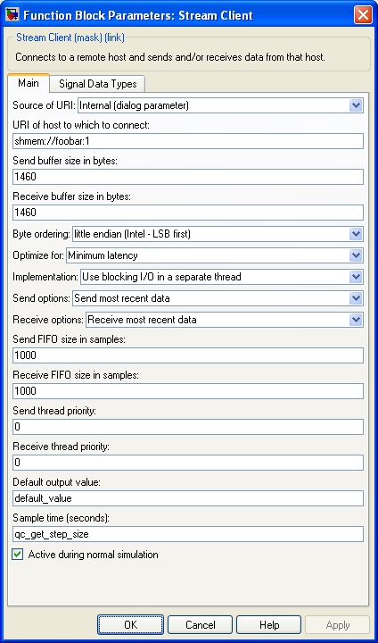
In addition to setting the Output data type field, the Stream Server and Stream Client blocks also need the Default output value parameter to be configured. For bus signals, this parameter must evaluate to a MATLAB structure containing the same fields as the bus signal itself. The data types and dimensions of those fields must also correspond to the bus signal. The MATLAB structure may be defined using the struct function in MATLAB or by defining it directly in the MATLAB command window and then using that workspace variable for this parameter.
For example, suppose the bus object contains three fields:
|
Field Name |
Field Data Type |
|---|---|
|
signal1 |
int16 |
|
signal2 |
double |
|
signal3 |
boolean |
then define its default value using code such as:
        default_value.signal1 = int16(0);
        default_value.signal2 = double(0);
        default_value.signal3 = false;
Enter "default_value" as the value of the Default output value parameter of the Stream Server or Stream Client block.
|
It is recommended that this variable be saved as part
of a MAT file (like the bus object). This MAT file should then be loaded from the
|
Copyright ©2026 Quanser Inc. This page was generated 2026-05-13. Submit feedback to Quanser about this page.
Link to this page.
