MATLAB Command Line
Click to copy the following command line to the clipboard. Then paste it in the MATLAB Command Window:
quarc_udp_server_demo; quarc_udp_client1_demo; quarc_udp_client2_demoQUARC UDP Server Demo
This example consists of three Simulink models: a server and two clients. It demonstrates how to use the Basic Communications blockset from the QUARC Targets Library to implement a UDP server capable of servicing multiple clients. In this particular example, the server exchanges data with two clients at the same time. It does not use the UDP broadcast feature. In general, the clients may be run on the local machine or on remote hosts. However, if the server is on Windows, the clients must be run on remote machines. For general information on the Basic Communications feature of QUARC, you can refer to the Basic Communications section. Be sure to investigate the Important Considerations section below to understand the design considerations that went into this demonstration.
Configuring the Demonstration
This demonstration can be run with all three models running on the same host, or it can be run with each client running on a remote target and communicating with the server on the local host. However, if the server is on Windows, then the clients must be run on remote targets. Linux does not have this restriction.
Running on Remote Hosts
To run the clients (or server) on remote targets, some configuration is required. Specifically:
To change the URI of each Stream Client block, double-click on the block to open its configuration dialog, as shown below.
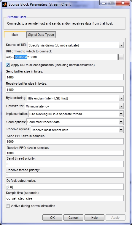
In the URI of host to which to connect field, replace localhost
in the URI with the host name or IP address of the host machine running the server.
Click OK to close the configuration dialog.
To modify the model URI of a client so that the client model is run on the desired remote target, open the Configuration Parameters dialog by selecting from the menu, or by pressing Ctrl+E. Then navigate to the Code Generation/Interface pane in the Select treeview.
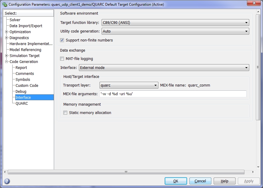
In the MEX-file arguments field, append the model URI of the remote target in single quotes. Be sure to separate the model URI from the model arguments with a comma. For example, if the remote machine is called "remhost", then a suitable model URI is "tcpip://remhost:17001" and the MEX-file arguments would look like:
'-w -d %d -uri %u','tcpip://remhost:17001'
For more information on model URIs and running QUARC models on remote targets, please refer to the Specifying a Model and/or Target URI page in the QUARC documentation. For a general discussion of model URIs, refer to Real-Time Code - the Model URI section of the Communicating with the Target documentation.
Configure the Stream Client block and model URI of each client model. Don't forget the firewall exceptions for UDP port 18000 and TCP ports 17000 and 17001.
Demonstration
Select from the menu of the diagram, or press Ctrl+B while each of the diagrams is the active window. A great deal of output will appear in the Diagnostic Viewer about the progress of the build. If you cannot see the Diagnostic Viewer, you can open it by selecting from the menu of the diagram, or clicking on the View Diagnostics hyperlink at the bottom of the diagram. If you have MATLAB R2013b or earlier then the output will appear in the MATLAB Command Window.
Double-click on the "Server Data" Scope in the quarc_udp_client1_demo.mdl and quarc_udp_client2_demo.mdl models to open their Scopes.
Double-click on the "Client 1 Data" and "Client 2 Data" Scopes in the quarc_udp_server_demo.mdl model to open its Scopes.
Click on the button or select from the menu of the diagrams to connect to the models.
Start the models by clicking on the button or selecting from the menu of the diagrams. Note that the order in which you start the models is not important. However, in practical situations, the server side should generally be running before the clients start. The item of the menu may also be used to both connect and start the model in one operation.
A sine wave of amplitude 4 will appear in the "Server Data" Scope of the two clients.
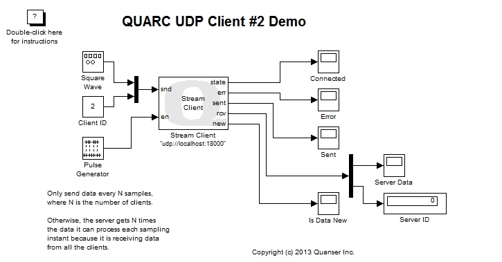
The server model receives a sawtooth wave from client #1 and a square wave from client #2.
Click on the button or select from the menu of the diagram to stop each model. The item of the menu may also be used.
Important Considerations
A number of important decisions were made in designing this demonstration to ensure that communications with multiple clients operated correctly. This section deals with the important factors that were considered and drove the implementation of this example. It will also highlight changes from the default settings that were required.
Peer Setting on the Server URI
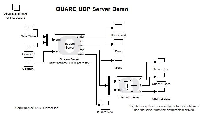
The URI of the Stream Server block in the quarc_udp_server_demo model has an additional option that is not part of the default settings. The peer option has been changed from the default to the value any.
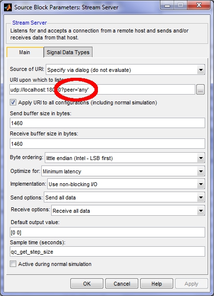
When the peer option is set to any the UDP protocol allows datagrams from any client to be received by the server. The default value of this option is one, which only accepts datagrams from the first client to communicate with the server. The default is one because it is assumed that the most common paradigm is only two models communicating.
With the peer option set to any,
the UDP server keeps track of the IP address of the client from whom it received a datagram most recently.
When the Stream Server block is given data to send at its snd input (and
its en input is true) then it sends the data to that client.
Thus, if it receives a datagram from client #1, it will send the data to client #1. If the next datagram it receives is from client #2, then it will send the data to client #2. Setting the peer option to any basically allows the UDP server to dynamically switch between clients as it receives datagrams from them. Without this option, the UDP server would only communicate with the first client to send it a datagram.
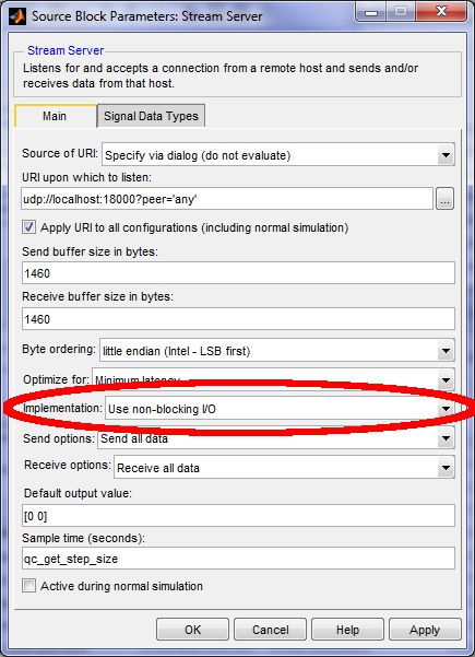
Non-blocking I/O for the Stream Server
A careful observer of the Stream Server parameters will notice that the Implementation parameter has been changed to from the default value of .
The Stream Server blocking I/O implementation suffers from possible client starvation in this particular communications topology and should not be used. The problem may be explained as follows. In the blocking I/O implementation, the Stream Server block creates two threads for handling communications: a send thread and a receive thread. These threads run asynchronously to the model and are not tied to a sampling period. Hence, the two threads can communicate at the fastest rate possible and do not interfere with the operation of the main diagram. Data is transferred between the two threads and the main diagram via first-in first-out (FIFO) queues at every sampling instant.
Normally, the fact that the multithreaded implementation can operate as fast as possible without interfering with the main diagram is a significant advantage and is the reason this implementation is the default. However, in this particular scenario it suffers from a shortfall.
Remember that the UDP server sends its data to the client whose datagram it received most recently. Since the receive thread in the multithreaded implementation of the Stream Server operates independent of the main diagram, it can receive multiple datagrams in the background. Suppose that it receives a datagram from client #1 and client #2, in that order, in between sampling instants. The receive thread places their data in the receive FIFO. The last datagram received is from client #2 so the server stores its IP address (due to the peer option being set to any). In other words, client #2 becomes the currently designated "peer".
On the next sampling instant, a sine wave data point is placed in the send FIFO and the send thread wakes up to transmit it to the client. The send thread transmits the data to client #2, since its IP address is the one stored.
Suppose the same situation occurs every time. Client #1 will never be sent any of the sine wave data from the server in this case because the datagram from client #2 always arrives immediately after its datagram and becomes the currently designated peer. Client #1 is starved of data from the server. The server does, however, receive all the data from both clients, because the receive thread stores all the data received in the receive FIFO.
In practice, this kind of starvation occurs intermittently. The server will appear to be serving each client somewhat equally and all of a sudden one client will get very little data and the sine wave it plots will appear jagged or even like infrequent random samples from the sine wave, while the other client displays a very smooth sine wave. After some time the situation may reverse and the client that was receiving little data begins displaying a smooth sine wave while the other client is starved for data. It should be possible to observe this behaviour by changing the Implementation option of the Stream Server block to Use blocking I/O in a separate thread.
Because of client starvation, the multithreaded implementation of the Stream Server block is not used. Instead, the non-blocking I/O implementation is used. In the non-blocking implementation the Stream Server block does not create any threads. Instead, it uses non-blocking I/O at each sampling instant to send and receive the data.
Now suppose the UDP datagrams arrive in the same order as they did in the above discussion - client #1's datagram arrives first, followed by client #2's datagram. On the next sampling instant, the Stream Server block receives client #1's datagram because it arrived first. The designated peer then becomes client #1 and the server sends a data point from its sine wave to client #1 in the same sampling instant.
On the next sampling instant, the datagram from client #2 is still in the stream buffer so the Stream Server block receives client #2's datagram next. The designated peer becomes client #2 and the server sends a data point from its sine wave to client #2 in the same sampling instant.
The server continues to process datagrams and send data to both clients equally. No client is starved for data and all the data from the clients is received. This fairness holds true regardless of the order in which the UDP datagrams arrive from the clients.
Decimating the Client Data
All three models run at the same sampling rate. Let the sampling rate be Ts. The Stream Server is receiving data from both clients at the same time. If both clients were sending data at the sampling rate Ts then the server would be receiving two UDP datagrams every sampling instant. However, the Stream Server block is only reading one datagram at a time from the stream. It can only read one datagram every Ts seconds, not two. If both clients were sending data every Ts seconds then the Stream Server block would not be able to keep up with the data from the clients.
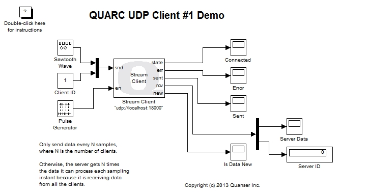
To avoid overwhelming the server with data, each client decimates the data it sends to the server. This decimation is accomplished using a Pulse Generator block connected to the en input of the Stream Client block.
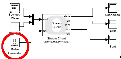
The Pulse Generator is configured to produce a pulse every N sampling instants, where N is the number of clients. In this case there are only two clients, so N is 2, and the Pulse Generator produces a pulse every other sampling instant.
As a result, each client is sending data every N*Ts seconds and the server receives a datagram every Ts seconds on average. The Stream Server block is not overwhelmed with data. Since the server will be alternating between clients (as discussed under "Non-blocking I/O for the Stream Server" above), each client will also receive decimated data. Each client will receive data every N*Ts seconds on average, just like the data received by the server for each client.
A natural question is why the Stream Server block should only process one datagram at a time. Why not configure it to receive N datagrams at a time, and then the N clients will not need to decimate their data? The problem with this solution is that not all clients may be running. For example, if the user stops one of the clients then the server will no longer be receiving N datagrams each sampling instant. Hence, it will have to wait for another sampling instant before it has a full N datagrams and can output anything from its rcv port. Since it is not uncommon for a client not to be running, particularly when the topology is started up or shut down, this situation will occur and is not ideal. It can however be detected by monitoring the new output of the Stream Server block.
Another possible alternative is to place the Stream Server block in a For Iterator Subsystem which executes N times, and to only enable sending of data on the first iteration. The loop could be aborted if the new output was false. This solution may effectively resolve the decimation issue but was not attempted for this example because of the added complexity.
Client and Server Identifiers
The Stream Server block does not provide any mechanism for knowing the IP address associated with each datagram received since it is a generic Stream block used for any communications protocol. As a result, the server cannot use the IP address to distinguish between the data sent from each client. In reality, an IP address is an inconvenient quantity anyways, as IP addresses are often dynamically assigned by DHCP.
To enable the server to associate each datagram with a particular client, an identifier value was added to the data sent by each client, as well as to the data sent by the server. The Server ID was not technically necessary, but was added for completeness because of its beneficial use in other UDP examples.
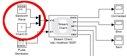
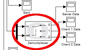
The above figure shows the client identifier being muxed into the data sent to the server. The server uses this identifier to route the client's data to its own Scope via a Demultiplexer block. The Demultiplexer block acts like a digital demultiplexer and routes its input signal to one of N outputs based on the selection input. The client identifier is passed to the selection input to route the data received to the appropriate plot.
Running the example on a different target
To run the example on a different target, refer to the instructions on the Running QUARC Examples on Remote Targets page.
Copyright ©2026 Quanser Inc. This page was generated 2026-05-13. Submit feedback to Quanser about this page.
Link to this page.