
Raspberry Pi Zero W
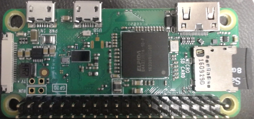
The Raspberry Pi Zero W is an embedded system built and sold by the Raspberry Pi Foundation, Inc. The Raspberry Pi Zero W driver provides access to the hardware I/O available on the Raspberry Pi Zero W board. The Raspberry Pi Zero W includes a BCM2835 ARMv6 processor (1 GHz, single core, 2M cache, 512 MB RAM). The I/O available with the Raspberry Pi Zero W include:
* Communications channels are accessed through the Stream API blocks, see Serial protocol,
SPI protocol and I2C protocol.
The QUARC driver name for this card is raspberry_pi_0 .
To select the Raspberry Pi Zero W board, select the QUARC raspberry_pi_0 board type from the drop-down list on the Main tab of the HIL Initialize block. Please note that only one raspberry_pi_0 "card" can be used on a Raspberry Pi Zero W at a time. The QUARC controller runs on the Raspberry Pi Zero W board and communicates with the hardware I/O directly.
| Note that the Linux Raspbian target must be selected to use the Raspberry Pi Zero W board. |
Communications
The communications ports provided on the Raspberry Pi Zero W board can be utilized through the QUARC Communications blockset and the Quanser Stream API (see QUARC Communications Protocols).
For SPI communications, a sample URI for communications would be:
spi://localhost:0?baud='1000000',phase='off',lsb='off',frame='0'
where the frame option selects the SPI CE line to frame the SPI bus transaction (0 or 1). Note that
the SPI port must be enabled using the raspi-config utility for SPI communications to be used. Once the SPI port is
enabled, the corresponding digital I/O (pins 19, 21, 23, 24 and 26) will no longer be available as digital I/O.
SPI can also be enabled via the /boot/config.txt file by setting spi=on in the
Device Tree Overlay parameters. For example:
dtparam=spi=on
After changing /boot/config.txt, reboot the Raspberry Pi for the changes to take effect.
For I2C communications, a sample URI for communications would be:
i2c://localhost:0?baud='400000',address=0x69
where the address option specifies the I2C slave address. Note that
the I2C port must be enabled using the raspi-config utility for I2C communications to be used. Once the I2C port is
enabled, the corresponding digital I/O (pins 3 and 5) will no longer be available as digital I/O.
To set the baud rate for the I2C, the /boot/config.txt file must be edited and the Raspbery Pi rebooted. For example, to enable I2C and set the I2C baud rate to 400000 baud, change the Device Tree Overlay parameters to:
dtparam=i2c_arm=on,i2c_arm_baudrate=400000
After changing /boot/config.txt, reboot the Raspberry Pi for the changes to take effect.
For serial communications, a sample URI for communications would be:
serial://localhost:1?baud='115200',word='8',parity='none',stop='1'
Configuring the Raspberry Pi Zero W to support serial communications is a bit more involved. First, use the raspi-config
utility to disable the serial port use by the kernel console. Then edit the /boot/config.txt file so
that:
enable_uart=1
Also add the line:
dtoverlay=pi3-disable-bt
in order to disable bluetooth, which makes use of the UART otherwise (see Pi Zero W WiFi interference with TTY). Alternatively, to maintain bluetooth and use the UART, use the lines:
dtoverlay=pi3-miniuart.txt
core_freq=250
Refer to this Raspberry Pi forum topic for details.
After changing /boot/config.txt, reboot the Raspberry Pi for the changes to take effect. Use the gpio readall command to confirm that the
TxD and RxD pins for the UART are in ALT0 mode. The serial port is /dev/ttyAMA0.
Clocks
The Raspberry Pi Zero W card does not support hardware clocks.
Analog Inputs
The Raspberry Pi Zero W card does not support analog inputs.
Analog Outputs
The Raspberry Pi Zero W card does not support analog outputs.
Digital Inputs
The Raspberry Pi Zero W supports 28 bidirectional digital I/O lines. Digital input channel numbers range from 0 to 27. Channels 0 and 1, however, are reserved for a HAT EEPROM I2C interface. A digital I/O line cannot be used as an input and output at the same time. Nor can it be used for communications (SPI, I2C or UART) or PWM at the same time.
Since the digital I/O lines may be individually programmed as inputs or
outputs on the Raspberry Pi Zero W, all channels which will be used for digital inputs
should be configured on the HIL Initialize
block's Digital Inputs tab. Set the Digital input channels field to all
the digital I/O channels that will be used as digital inputs on the board for the current diagram. For example, enter
2:4 to designate channels 2 through 4 as digital inputs. Specify
[2, 4, 5] to indicate that channels 2, 4 and 5 are to be configured
as digital inputs.
Digital Outputs
The Raspberry Pi Zero W supports 28 bidirectional digital I/O lines. Digital output channel numbers range from 0 to 27. Channels 0 and 1, however, are reserved for a HAT EEPROM I2C interface. A digital I/O line cannot be used as an input and output at the same time. Nor can it be used for communications (SPI, I2C or UART) or PWM at the same time.
Since the digital I/O lines may be individually programmed as inputs or outputs
on the Raspberry Pi Zero W, all the channels which will be used for digital outputs should be configured
on the HIL Initialize block's
Digital Outputs tab. Set the Digital output channels
field to all the bidirectional digital I/O channels that will
be used as digital outputs on the board for the current diagram. For example, enter
2:4 to designate channels 2 through 4 as digital outputs. Specify
[2, 4, 5] to indicate that channels 2, 4 and 5 are to be configured
as digital outputs.
To set the digital output values when the model is loaded or unloaded, set the Initial digital outputs and Final digital outputs to the desired values respectively. If the vectors specified in these fields are shorter than the channel vector, the value of the last element in the vector will be used for the rest of the channels. Hence, a scalar value will apply to all channels specified in the Digital output channels field.
Encoder Inputs
The Raspberry Pi Zero W card does not support encoder inputs.
PWM Outputs
The Raspberry Pi Zero W driver supports up to 2 PWM output channels. Hence, PWM output channels range from 0 to 1. Each PWM channel is completely independent and can have its own duty cycle and frequency.
Before the PWM channels may be used, they must be configured in the /boot/config.txt file and in the board-specific
options. The /boot/config.txt file must be edited with root privileges. For example, to use the vi editor,
enter the command:
sudo vi /boot/config.txt
in a terminal window.
The lines which must be added to the /boot/config.txt file depend on the number of PWM channels desired, and the pins to which they are assigned. The following table documents the lines that must be added to the /boot/config.txt file for each combination of options:
|
PWM 0 |
PWM 1 |
Line to Add |
|---|---|---|
|
disabled |
disabled |
Do not add any lines |
|
GPIO 12 |
disabled |
|
|
GPIO 18 |
disabled |
|
|
disabled |
GPIO 13 |
|
|
disabled |
GPIO 19 |
|
|
GPIO 12 |
GPIO 13 |
|
|
GPIO 12 |
GPIO 19 |
|
|
GPIO 18 |
GPIO 13 |
|
|
GPIO 18 |
GPIO 19 |
|
| Note that once a GPIO is configured as a PWM channel then it will no longer be recognized as a digital I/O line. |
In order to configure the PWM mode or frequency, or to set the value of the PWM outputs when the model is loaded or unloaded, the PWM
outputs must be configured on the HIL Initialize block's
PWM Outputs tab. Set the PWM output channels field to all the PWM output channels that will be used on the
board for the current diagram. For example, enter 0:1 to indicate channels 0 and 1. Specify 1 to indicate channel 1 alone.
The PWM outputs are generic PWM outputs that are capable of producing the standard analog ESC protocols, namely standard PWM (1000us to 2000us), Oneshot125 (125us to 250us), Oneshot42 (42us to 84us) and Multishot (5us to 25us). They may also be used to drive R/C servos.
The PWM parameters for each of these protocols are tabulated below:
|
Protocol |
PWM Frequency |
Pulse Time Range |
Duty Cycle Range |
|---|---|---|---|
|
Standard PWM |
50 Hz (20ms) |
0.001 to 0.002 seconds (1ms to 2ms) |
0.05 to 0.1 (5% to 10%) |
|
Oneshot125 |
2000 Hz (500us) |
125e-6 to 250e-6 seconds (125us to 250us) |
0.25 to 0.5 (25% to 50%) |
|
Oneshot42 |
11905 Hz (84us) |
42e-6 to 84e-6 seconds (42us to 84us) |
0.25 to 0.5 (25% to 50%) |
|
Multishot |
20000 Hz (50us) |
5e-6 to 25e-6 seconds (5us to 25us) |
0.1 to 0.5 (10% to 50%) |
The PWM outputs are not restricted to these parameter values as they are generic PWM outputs. The maximum output frequency is 50 MHz. The number of bits of resolution decreases with increasing PWM output frequency.
Set the PWM output frequency (a.k.a., pulse rate) in the "Frequencies in Hz or duty cycle" field. The PWM output mode is typically set to duty cycle mode (0) or time mode (4) when driving ESCs or R/C servos. Set the Initial PWM outputs and Final PWM outputs fields to the desired initial and final output values respectively. The interpretation of these output values depends on the PWM mode selected. If the vectors specified in these fields are shorter than the channel vector, the value of the last element in the vector will be used for the rest of the channels. Hence, a scalar value will apply to all channels specified in the PWM output channels field.
Other Inputs
The Raspberry Pi Zero W card does not support other inputs.
Other Outputs
The Raspberry Pi Zero W card does not support other outputs.
Interrupts
The Raspberry Pi Zero W card, or its driver, does not support any interrupt sources.
Watchdog
The Raspberry Pi Zero W card does not support a watchdog timer.
Board-Specific Options
The Raspberry Pi Zero W has a number of board-specific options to control specialized functionality of the board. These options configure the PWM.
pwm0_en
This option is a boolean value that enable or disables PWM 0. If PWM 0 is disabled then the PWM pin may be used as a regular digital I/O. Valid values are 0, 1, false, true, off, on, no or yes.
pwm1_en
This option is a boolean value that enable or disables PWM 1. If PWM 1 is disabled then the PWM pin may be used as a regular digital I/O. Valid values are 0, 1, false, true, off, on, no or yes.
pwm0_pin
This option determines which pin will be used for PWM 0. Valid values are 12 or 18 corresponding to GPIO 12 or GPIO 18 respectively.
| Note that once a GPIO is configured as a PWM channel then it will no longer be recognized as a digital I/O line. |
pwm1_pin
This option determines which pin will be used for PWM 1. Valid values are 13 or 19 corresponding to GPIO 13 or GPIO 19 respectively.
| Note that once a GPIO is configured as a PWM channel then it will no longer be recognized as a digital I/O line. |
Properties
The Raspberry Pi Zero W card does not support any properties.
Connectors
The Raspberry Pi Zero W board has one connector for expansion I/O. The pinouts for this connector are listed below. Note that all pins are 3.3V and are not 5V tolerant unless marked otherwise. Exceeding these voltages may damage the board!
Raspberry Pi GPIO Connector
GPIO 21 ↔ | 40 | 39 | ― Ground |
GPIO 20 ↔ | 38 | 37 | ↔ GPIO 26 |
GPIO 16 ↔ | 36 | 35 | ↔ GPIO 19 / → PWM 1 |
Ground ― | 34 | 33 | ↔ GPIO 13 / → PWM 1 |
PWM 0 ← / GPIO 12 ↔ | 32 | 31 | ↔ GPIO 6 |
Ground ― | 30 | 29 | ↔ GPIO 5 |
ID SC / GPIO 1 ↔ | 28 | 27 | ↔ GPIO 0 / ID SD |
SPI CE1 ← / GPIO 7 ↔ | 26 | 25 | ― Ground |
SPI CE0 ← / GPIO 8 ↔ | 24 | 23 | ↔ GPIO 11 / → SPI SCLK |
GPIO 25 ↔ | 22 | 21 | ↔ GPIO 9 / ← SPI MISO |
Ground ― | 20 | 19 | ↔ GPIO 10 / → SPI MOSI |
GPIO 24 ↔ | 18 | 17 | ― 3.3V |
GPIO 23 ↔ | 16 | 15 | ↔ GPIO 22 |
Ground ― | 14 | 13 | ↔ GPIO 27 |
PWM 0 ← / GPIO 18 ↔ | 12 | 11 | ↔ GPIO 17 |
UART RXD → / GPIO 15 ↔ | 10 | 9 | ― Ground |
UART TXD ← / GPIO 14 ↔ | 8 | 7 | ↔ GPIO 4 |
Ground ― | 6 | 5 | ↔ GPIO 3 / I2C SCL |
5V ― | 4 | 3 | ↔ GPIO 2 / I2C SDA |
5V ― | 2 | 1 | ― 3.3V |
Legend
→▯← | = | input |
←▯→ | = | output |
↔▯↔ | = | bidirectional I/O |
= | 3.3V signal | |
= | power | |
= | ground |
Targets
|
Target |
Supported |
Comments |
|---|---|---|
|
No |
Not supported. |
|
|
No |
Not supported. |
|
|
No |
Not supported. |
|
|
No |
Not supported. |
|
|
No |
Not supported. |
|
|
No |
Not supported. |
|
|
No |
Not supported. |
|
|
No |
Not supported. |
|
|
No |
Not supported. |
|
|
No |
Not supported. |
|
|
No |
Not supported. |
|
|
No |
Not supported. |
|
|
No |
Not supported. |
|
|
No |
Not supported. |
|
|
No |
Not supported. |
|
|
Rapid Simulation (RSIM) Target |
Yes |
Supported with no communication to the hardware. |
|
Normal simulation |
Yes |
Supported with no communication to the hardware. |
See Also
Copyright ©2026 Quanser Inc. This page was generated 2026-05-13. Submit feedback to Quanser about this page.
Link to this page.
