
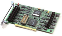
Sensoray Model 626
The Sensoray Model 626 is an multifunction I/O card for PCI slots. For more information, visit the website for the Sensoray Model 626.
The QUARC driver name for this card is sensoray_model_626.
 The Sensoray Model 626 data acquisition card (i.e., HIL board) has been deprecated as it is only supported under 32-bit Windows XP.
Installation Requirements
 In order to use the Sensoray Model 626 in QUARC, the card driver must be installed. If you are migrating from WinCon, then you will also need
to follow this installation proceedure as it differs from the WinCon driver. You can download the SDK from
http://www.sensoray.com/downloads/sdk_626_win_1.0.5.zip. Follow the driver
installation instructions inside the zip file Windows\Install 98-ME-2000-XP folder. You will need to reboot your computer after installing
the driver.
In order to use the Sensoray Model 626 in QUARC, the card driver must be installed. If you are migrating from WinCon, then you will also need
to follow this installation proceedure as it differs from the WinCon driver. You can download the SDK from
http://www.sensoray.com/downloads/sdk_626_win_1.0.5.zip. Follow the driver
installation instructions inside the zip file Windows\Install 98-ME-2000-XP folder. You will need to reboot your computer after installing
the driver.
Configuration
To select the Model 626, select the QUARC driver sensoray_model_626 from the drop-down list on the Main tab of the HIL Initialize block.
If you only have one card installed in your system, then you can enter 0 for the Board identifier and the QUARC driver will automatically find the card. If more than one card is installed in your system, that you must identify each board by its slot and bus number. To determine the bus and slot numbers of your installed cards, open the Device Manger in the Windows control panel. You will find the card installed under the Sound, video and game controllers group as shown below:
Double click on the device to open the device properties. Take note of the slot and bus number as shown in the example below:
Back on the Main tab of the HIL Initialize block, enter the following into the Board identifier field without the quotes "slot=1;bus=7" (substituting the slot and bus number that you previously noted). Note that there are no spaces in the string, and the text is all lowercase. The slot and bus number may or may not have any physical relation to the actual location of the card in your PC.
Clocks
The Model 626 has 6 counters which can be configured for use as clocks, or quadrature decoding counters.
Using the Clocks tab of the HIL Initialize block, enter the applicable
counter numbers in the Hardware clocks field. For example, enter 1:5 to indicate channels 1 through 5. Specify [0, 4, 5]
to indicate channels 0, 4 and 5. Next, specify the mode of the counter in the Clock modes field. If the vector specified in
this field is shorter than the channel vector, then the value of the last element in the vector will be used for the rest of the channels.
Hence, a scalar value will apply to all channels specified in the Clock mode field. Unspecified counters will default to
a timebase mode.
Analog Inputs
The Model 626 supports 16 analog inputs (channels 0 to 15) with 16-bit resolution.
The valid input ranges are ±10V, and ±5V.
To change from the default range of ±10V, set the selected channels in the
Analog Inputs tab of the HIL Initialize block to the channels
in use. For example, enter 4:7 to indicate channels 4 through 7. Specify [0, 4, 5] to indicate channels 0, 4 and 5. Next set
the analog input maximum and minimum.
Note that the Model 626 is designed to support oversampling. If a single channel is referenced multiple times in a HIL Read Analog block, it will be read multiple times during a single time sample. This can be useful for averaging to reduce noise. If an identical value is required for multiple instances of a single channel, it is recommended that you use an external Mux block from Simulink's Signal Routing block group.
| To get the best performance, all analog reads should be performed from a single HIL Read Analog block. If multiple analog input blocks must be used, the fastest sample period that can be used is approximately 2 ms times the number of HIL Read Analog blocks. This sample period limitation does not apply when a single HIL Read Analog block is used. |
| There is a known limitation of Sensoray's driver which interferes with the diagram timing (even with a hardware timebase) when using more than one analog input. If using more than one analog input, it is recommended that you check the actual sample period of your diagram using a Sample Time block to ensure it is within an acceptable tolerance. |
Analog Outputs
The Model 626 supports 4 analog outputs (channels 0 to 3) with 14-bit resolution. The only valid output range is ±10V, so it is not necessary to set the range. Note that the analog output channels are updated sequentially for this card so there will be a small time difference from when the first channel is modified to when the last channel is modified.
If the update order is important for your application, list the desired sequence in the Analog output channels field in the Analog Outputs tab of the HIL Initialize.
In order to have analog outputs set to a particular voltage when the model is loaded or unloaded, the analog outputs must be configured on
the HIL Initialize block's Analog Outputs tab. Set the
Analog output channels field to all the analog output channels that will be used on the board for the current diagram.
For example, enter 4:7 to indicate channels 4 through 7. Specify [0, 4, 5] to indicate channels 0, 4 and 5. Set the
Analog output maximums field to 10 and set the Analog output minimums field to -10, to
match the ±10V range of the analog outputs. Finally, set the Initial analog outputs and
Final analog outputs to the desired voltages. If the vectors specified in these fields are shorter than the channel
vector than the value of the last element in the vector will be used for the rest of the channels. Hence, a scalar value will apply to all
channels specified in the Analog output channels field.
Digital Inputs
The Model 626 supports 48 digital lines (lines 0 to 47). The digital ports on this card use an open-collector design with an internal pull-up. When a line is configured as an input, it will be pulled high internally, so it must be driven by a low impedance source to pull it low. A digital input can read the same line that is used for a digital output.
Digital Outputs
The Model 626 supports 48 digital lines (lines 0 to 47). The digital ports on this card use an open-collector design with an internal pull-up. When configured as a digital output, it should be only used to drive high impedance devices. Setting the output to 1 is also corresponds to the mode used to configure the port as a digital input, so it is possible to use the digital lines on the Model 626 for bi-directional communication.
To set the digital output values when the model is loaded or unloaded, first configure the channels to be used for digital outputs on the
the HIL Initialize block's Digital Outputs tab. For example,
enter 2:5 to designate lines 2 through 5 as digital outputs. Specify [0, 4, 5] to indicate that lines 0, 4 and 5 are to be
configured as digital outputs. Next, set the Initial digital outputs and Final digital outputs to the
desired values respectively. If the vectors specified in these fields are shorter than the channel vector then the value of the last element
in the vector will be used for the rest of the channels. A scalar value will apply to all channels specified in the
Digital output channels field.
Encoder Inputs
The Model 626 supports 6 quadrature encoder inputs with 24-bit count values (channels 0 to 5).
The quadrature decoders require clock resources, so to utilize an encoder input, you must first configure the corresponding clock as an encoder on the Clocks tab in the HIL Initialize, and check the box to Set the clock parameters at model start.
In order change the default quadrature when the model is loaded, you must specify the encoder input channels on the HIL Initialize block's Encoder Inputs tab, then specify the corresponding quadrature for each channel. If the vectors specified in these fields are shorter than the channel vector, then the value of the last element in the vector will be used for the rest of the channels. Hence, a scalar value will apply to all channels specified in the Encoder input channels field. Finally, check the box to Set the encoder input parameters at model start. Note that if the initial encoder counts are not specified, the encoder will continue to maintain its count as long as the Model 626 is powered, including any changes made when a model is not active.
The Model 626 supports 1X quadrature, 2X quadrature and 4X quadrature (default). The Model 626 does not support a non-quadrature mode (count and direction) or encoder filtering.
In order set the encoder counters to a particular count when the model is loaded, you must specify the encoder input channels on the HIL Initialize block's Encoder Inputs tab, then specify the corresponding inital encoder counts. If the vectors specified in these fields are shorter than the channel vector, then the value of the last element in the vector will be used for the rest of the channels. Hence, a scalar value will apply to all channels specified in the Encoder input channels field. Finally, check the box to set the initial encoder counts at model start. Note that if the initial encoder counts are not specified, the encoder will continue to maintain its count as long as the Model 626 is powered, including any changes made when a model is not active.
PWM Outputs
The Sensoray Model 626 card does not support PWM outputs.
Other Inputs
The Sensoray Model 626 card does not support other inputs.
Other Outputs
The Sensoray Model 626 card does not support other outputs.
Interrupts
The Sensoray Model 626 card, or its driver, does not support any interrupt sources.
Watchdog
The Sensoray Model 626 card does not support a watchdog timer.
Board-Specific Options
The Sensoray Model 626 card does not support any board-specific options.
Properties
The Sensoray Model 626 card does not support any properties.
Targets
|
Target |
Supported |
Comments |
|---|---|---|
|
Yes |
Only supported in Windows XP. |
|
|
No |
Not supported. |
|
|
No |
Not supported. |
|
|
No |
Not supported. |
|
|
No |
Not supported. |
|
|
No |
Not supported. |
|
|
No |
Not supported. |
|
|
No |
Not supported. |
|
|
No |
Not supported. |
|
|
No |
Not supported. |
|
|
No |
Not supported. |
|
|
No |
Not supported. |
|
|
No |
Not supported. |
|
|
No |
Not supported. |
|
|
No |
Not supported. |
|
|
Rapid Simulation (RSIM) Target |
Yes |
Supported with no communication to the hardware. |
|
Normal simulation |
Yes |
Supported with no communication to the hardware. |
Copyright ©2026 Quanser Inc. This page was generated 2026-05-13. Submit feedback to Quanser about this page.
Link to this page.
