
Vision Detect Landmark

|
This block is currently a beta version. If you are using this block, we would appreciate any feedback at tech@quanser.com. |
Detects the specified landmark.
Library
QUARC Targets Beta/Image Processing/Open Source Computer Vision MATLAB Command Line Click to copy the following command line to the clipboard. Then paste it in the MATLAB Command Window: qc_open_library('quarc_library_beta/Image Processing/Open Source Computer Vision')
Description
The Vision Detect Landmark block segments the specified landmark from an input image. The following steps are performed to detect the landmark blobs from an input image: 1) color to binary image conversion of the input image, 2) edge detection and morphological closing operation on binary image for noise detection, 3) noise reduction operation based on the allowable noise to image area ratio, 4) landmark detection based on the specified color information and allowable size of the landmark blobs, 5) morphological operation for combining closely located landmark blobs, and 6) landmark blob tracking between successive frames. The outputs of this block include color and binary images of the landmark, feature vector of the landmark, and error signal.
In order to use this block, be sure to follow the instructions described on the Vision Capture Image page, and take careful note of the limitations.
Input Ports
image
A handle to an image that uses OpenCV (Open Source Computer Vision) IplImage structure.
Output Ports
color_blobs
Color image of the detected landmark.
binar_blobs
Binary image of the detected landmark.
feature_vec
Feature vector of the detected landmark. It has six elements. The first three elements show the area (in pixels), distance (in pixels), and angular orientation (in degrees) of the continuously tracked landmark blob. The landmark blob is tracked using the minimum root-mean-square error between [area distance angular_orientation] vectors. If the landmark blobs are detected for the first time or no match is found compared to the last frame, the first three elements represent the landmark blob having maximum area. The fourth element shows root-mean-square error for the selected landmark blob, the fifth element indicates how many times the blob has been continuously tracked, and the last element stands for the total number of landmark blobs obtained in the current frame.
err
This signal is negative in case of error.
Parameters and Dialog Box
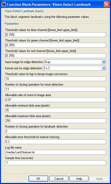
Threshold values for blue channel
Indicate lower limit and higher limit of blue color index of the landmark.
Threshold values for green channel
Indicate lower limit and higher limit of green color index of the landmark.
Threshold values for red channel
Indicate lower limit and higher limit of red color index of the landmark.
Input image for edge detection
The edge detection process has the following options for input image types: Gray, B(blue), G(green), and R(red) image planes of the input image.
Kernel size for edge detection
Defines the size of edge-detector kernel used for convolution.
Threshold value for bgr to binary image conversion
Specifies the threshold value used for color input image to binary image conversion. The parameter value must be 0 to 255.
Number of closing operation for noise detection
Specifies the number of morphological closing operation for noise detection.
Allowable ratio of noise to image area
This ratio is used to filter out noise from the input image. The binary blobs having higher ratios are discarded for ladmark detection process.
Allowable minimum blob area
Specifies the minimum blob area in pixels. Binary blobs having areas lower than the minimum threshold are discarded for landmark detection.
Allowable maximum blob area
Specifies the maximum blob area in pixels. Binary blobs having areas greater than the maximum threshold are discarded for landmark detection.
Number of closing operation for landmark detection
Specifies the number of morphological closing operation for landmark detection.
Allowable error threshold for feature tracking
The threshold value of root-mean-square error is used to track a landmark blob between successive frames.
Log file name
This file stores the feature vector obtained at each sampling instance. An increasing index value is added in front of each feature vector to indicate the sampling instance.
Sample time
The sample time of the block. A sample time of 0 indicates that the block will be treated as a continuous time block. A positive sample time indicates that the block is a discrete time block with the given sample time. A sample time of -1 indicates that the block inherits its sample time.
Targets
|
Target Name |
Compatible* |
Model Referencing |
Comments |
|---|---|---|---|
|
No |
No |
Not supported. |
|
|
No |
No |
Not supported. |
|
|
Yes |
Yes |
||
|
Yes |
Yes |
||
|
Yes |
Yes |
||
|
Yes |
Yes |
||
|
Yes |
Yes |
||
|
Yes |
Yes |
||
|
Yes |
Yes |
||
|
Yes |
Yes |
||
|
Yes |
Yes |
||
|
Yes |
Yes |
||
|
Yes |
Yes |
||
|
No |
No |
Not supported. |
|
|
Rapid Simulation (RSIM) Target |
No |
No |
Not supported. |
|
S-Function Target |
No |
N/A |
Old technology. Use model referencing instead. |
|
Normal simulation |
Yes |
Yes |
Copyright ©2026 Quanser Inc. This page was generated 2026-05-13. Submit feedback to Quanser about this page.
Link to this page.