
Starting with a Blank VI
Since the RCP Toolkit uses a minimal set of VIs to access hardware and other operations, it is
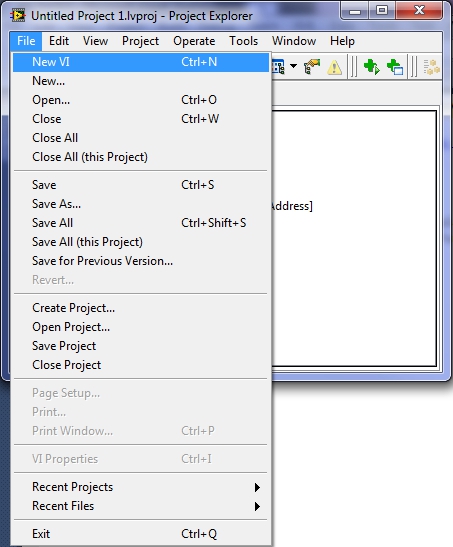
easy to create a new VI from scratch that uses the RCP Toolkit. To begin with, create a blank
via by selecting from the LabVIEW or project menu, as illustrated below.
If using a project, be sure to select the My Computer section.
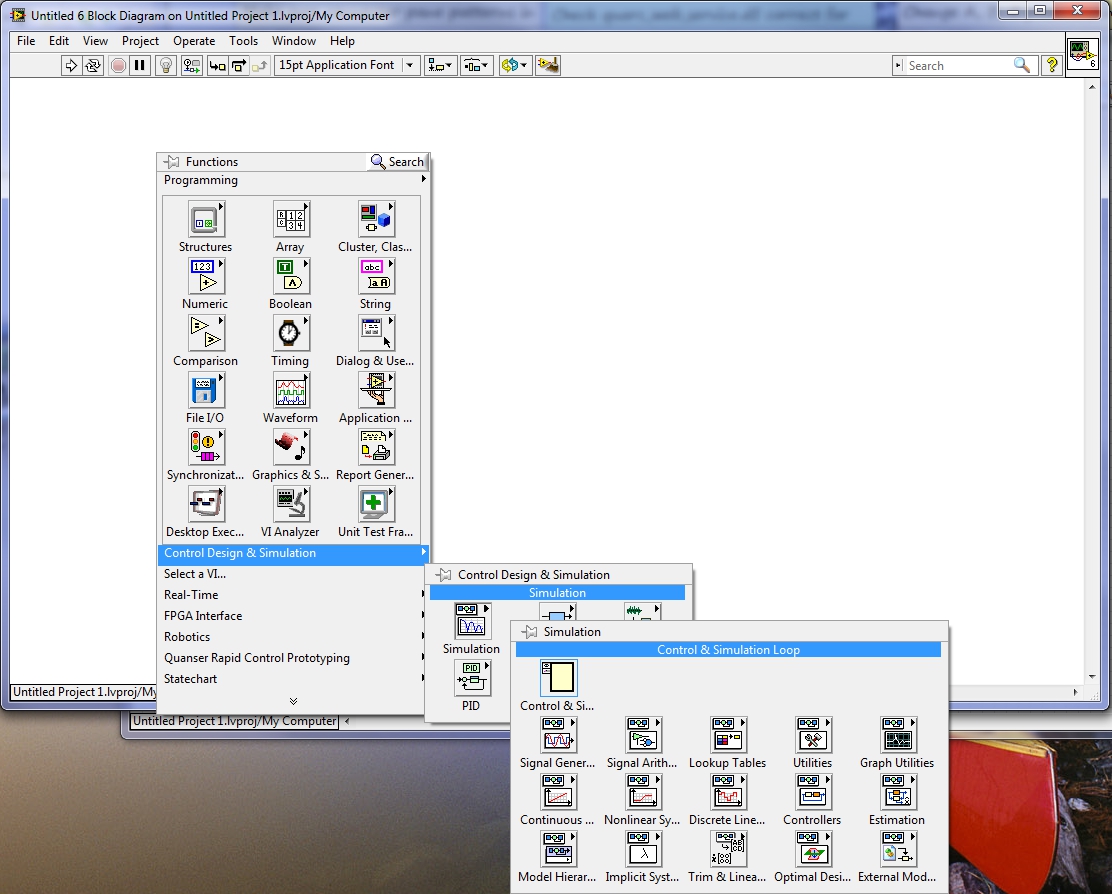
Right-click in the block diagram and select the Control & Simulation Loop from the palette.
Click in the block diagram and drag the mouse to form a rectangle the size of the loop that you want. Release the mouse to place the Control Design & Simulation Loop in the diagram with the chosen size.
Double-click on the left input to the Control Design & Simulation Loop or right-click on the border of the loop and select from the context menu:
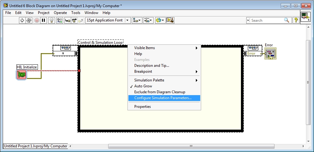
The Configure Simulation Parameters dialog will open. On the Simulation Parameters tab, set the parameters as follows:
|
Parameter Name |
Parameter Value |
|---|---|
|
Final Time |
Inf |
|
ODE Solver |
Runge-Kutta 1 (Euler) |
|
Step Size (s) |
0.002 |
|
Auto Discrete Time |
Checked |
The final settings on the Simulation Parameters tab should look like this:
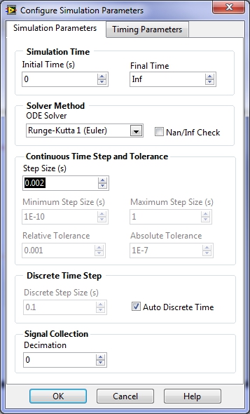
Other values for the solver and step size may be chosen, but a fixed-step solver should be used. A step size of 2ms is usually a good starting point for many control systems and should be achievable on both Windows and the CompactRIO.
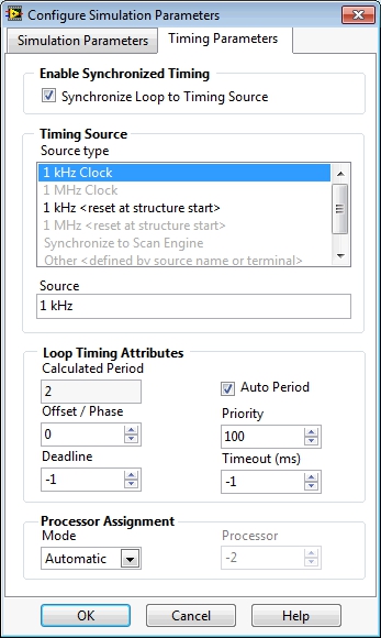
On the Timing Parameters tab, set the parameters as follows:
|
Parameter Name |
Parameter Value |
|---|---|
|
Synchronize Loop to Timing Source |
checked |
|
Auto Period |
checked |
The final settings on the Timing Parameters tab should look like this:
Click to save the settings.
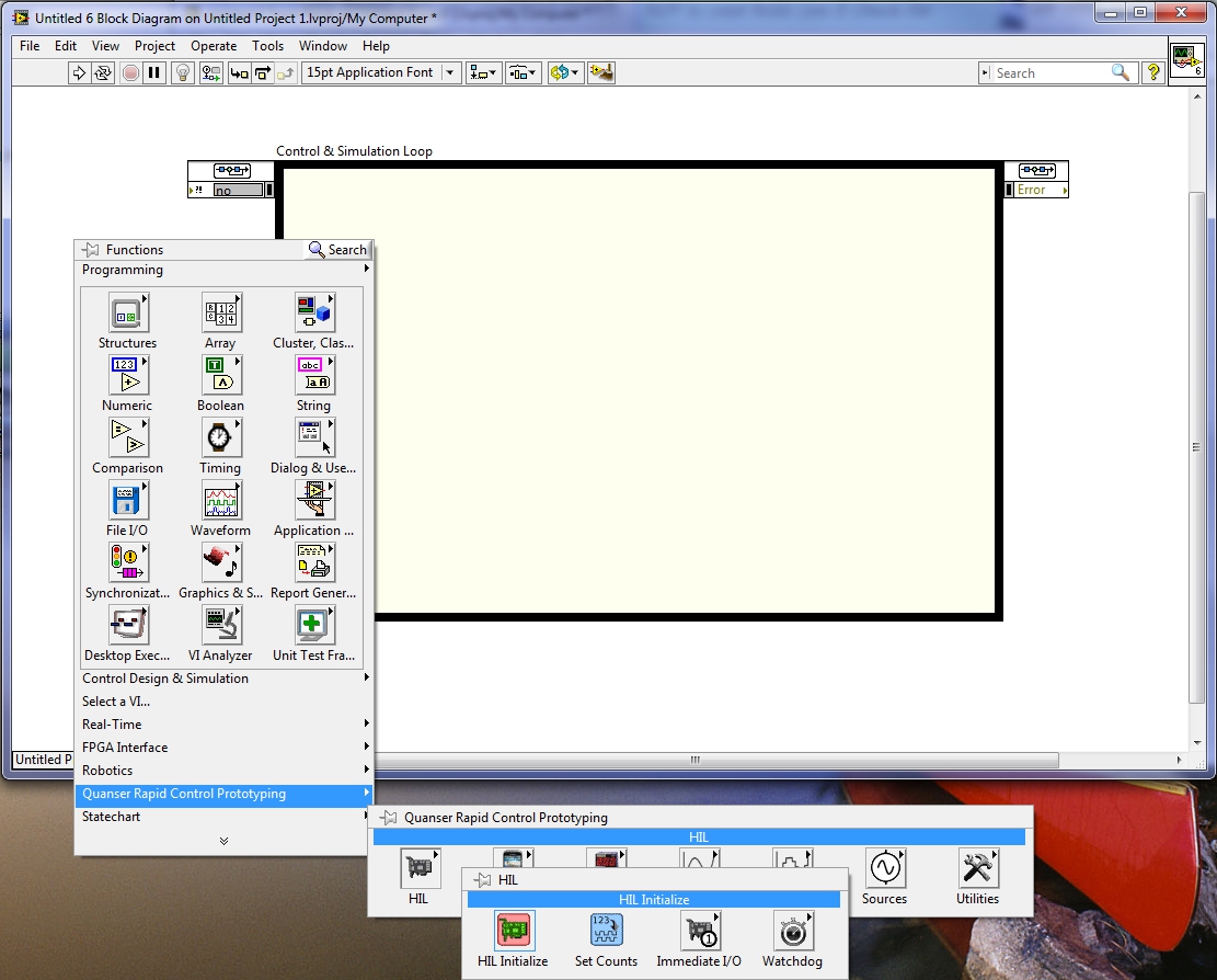
To access hardware using the RCP Toolkit, a HIL Initialize VI is required. Right-click to the left of the Control Design & Simulation Loop in the diagram and choose the HIL Initialize VI from the palette, as depicted below:
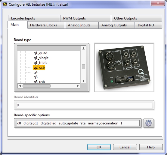
After placing the HIL Initialize VI in the diagram, double-click on it and choose the data acquisition card you intend to use. For example, select the Q2-USB as shown below:
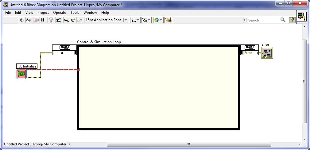
Click to save the changes. Wire the error out terminal of the HIL Initialize VI to the Error input terminal of the Control Design & Simulation Loop. Also wire the board out terminal to the edge of the loop. Finally, create an error indicator at the output of the Control Design & Simulation Loop as shown:
| Always wire the output of the Control Design & Simulation Loop to an error indicator. Do not depend on automatic error handling to report errors because the error dialog interrupts the execution of the VI. Interrupting a running control system is dangerous, so automatic error handling must be avoided. Quanser recommends adding a HIL Watchdog VI to the loop as well if the hardware supports it to ensure hardware outputs are reset to zero in such instances. |
The VI is now ready for hardware access. Use the CL HIL Read and CL HIL Write VIs in the palette for single sample reads and writes from any or all channels of the data acquisition card.
Copyright © Quanser Inc. This page was generated 2024-11-15. Submit feedback to Quanser about this page.
Link to this page.
