
Using Project Templates
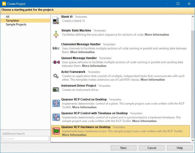
To facilitate creating projects for new control systems, the RCP Toolkit supplies convenient project templates. To use a project template, simply select from the menu. The project templates supplied with the RCP Toolkit appear under the Templates category. Select the Quanser RCP Hardware on Desktop template, for example, as illustrated below:
Once a template has been selected, press to enter the details of the project. The name of the project as well as the root directory for the project can be modified, as depicted in the following figure:
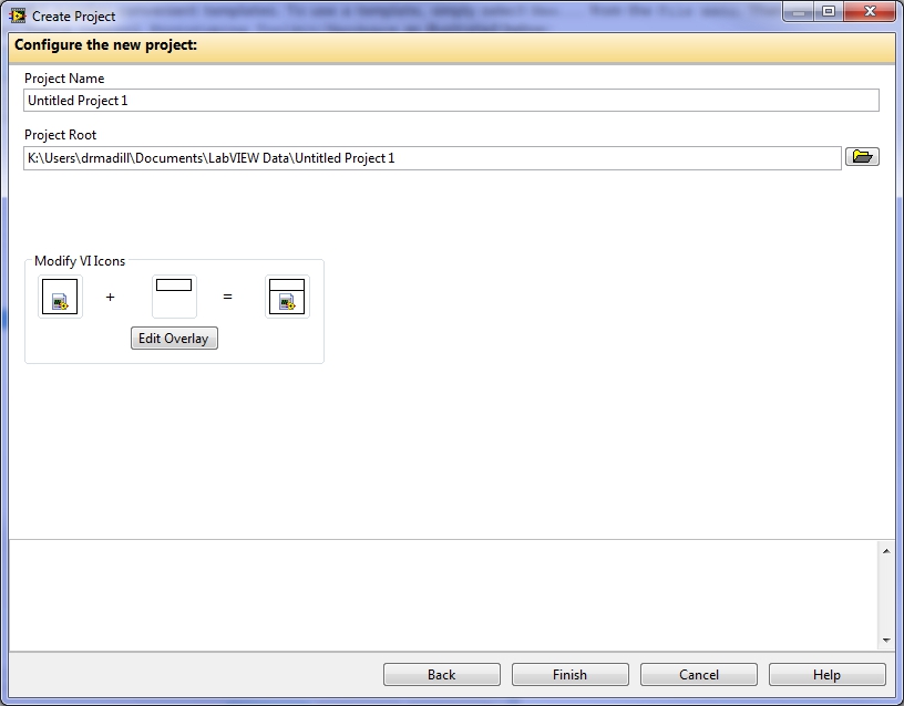
The overlay for VI icons can also be edited. The project template takes the default icon supplied with the VIs contained in the project template and merges it with the overlay configured on this page.
After setting the project name and root directory, click the button to instantiate the project. A sample project created using these steps is shown below:
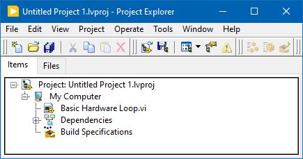
Note that the created project contains the Basic Hardware Loop VI in the My Computer section
of the project.
Below is the control diagram of the Basic Hardware Loop VI:
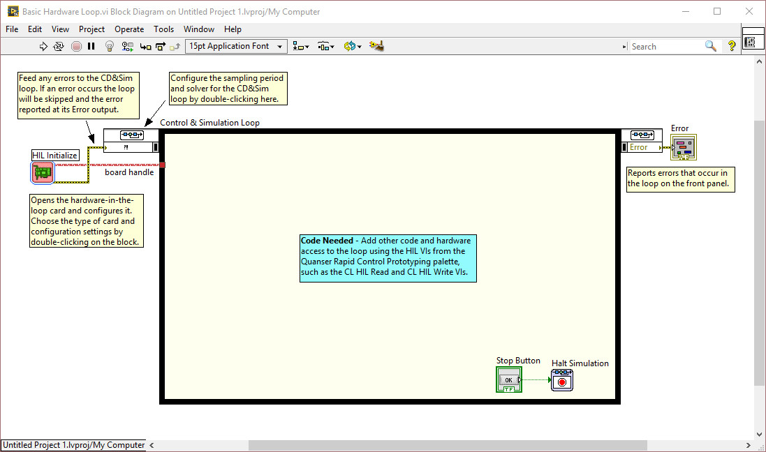
The HIL Initialize VI initialize the hardware. The data acquisition card is selected in this VI's configuration parameters.
Save the project so that these settings are preserved. Close the VI and project. The VI is now ready to run.
Running the Basic Hardware Loop
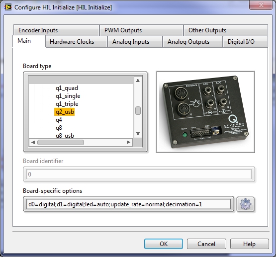
To configure the Basic Hardware Loop VI, open the project and block diagram of the Basic Hardware Loop VI created in the last section. Double-click on the HIL Initialize VI and select the board type corresponding to the data acquisition card that you have installed on your desktop machine. Click OK to accept the changes. The figure below shows the HIL Initialize configuration dialog with the Quanser Q2-USB card selected:
To have the Control and Simulation Loop perform actual logic, update the Basic Hardware Loop VI to resemble the following:
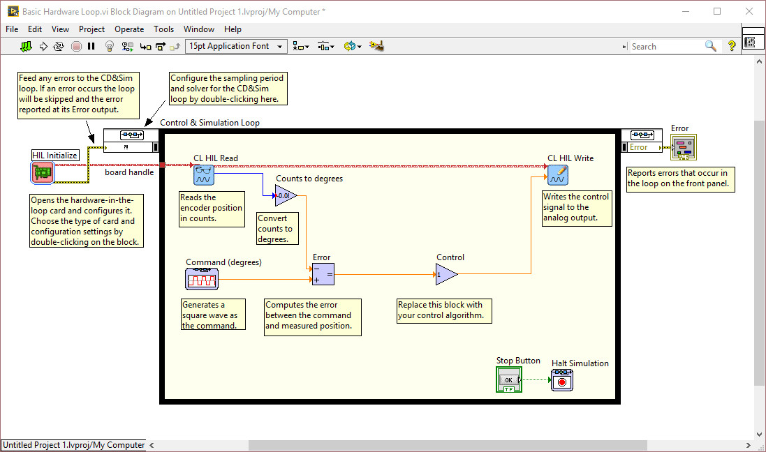
The CL HIL Read VI reads the encoder signal used to measure position. The same VI can be used to read from any or all of the inputs of the selected data acquisition card. The raw encoder position is scaled by the Counts to degrees VI to be in degrees. The scale factor will likely have to be replaced for each application.
The CL HIL Write VI writes to the analog output used to drive the motor. The same VI can be used to write to any or all of the outputs of the selected data acquisition card.
The default controller consists of a simple proportional controller with unity gain. At the very least, the controller gain Control will need to be replaced with a more sophisticated control strategy.
The reference signal is currently a signal generator VI called Command (degrees). A square wave is suitable for looking at step responses when tuning the controller. However, it will likely need to be replaced as well for the end application.
The above changes to the VI is based on the Basic Control Loop VI template supplied with the RCP Toolkit. Refer to the Using VI Templates page for more information about tailoring this VI to suite your needs.
The VI is now ready to run.
Copyright © Quanser Inc. This page was generated 2024-11-15. Submit feedback to Quanser about this page.
Link to this page.