
ATS AFR Tool
Interfaces to the ATS AFR Tool.
Library
QUARC Applications/ATS MATLAB Command Line Click to copy the following command line to the clipboard. Then paste it in the MATLAB Command Window: qc_open_library('quarc_library_applications/ATS')
Description
The ATS AFR Tool block sends position or velocity commands to each axis of the ATS AFR Tool and receives positions, velocities and torques as well as sundry status flags for each of the 19 axes. It can also interface to a simulation of the AFR Tool implemented using the AFR Tool Simulation block.
Input Ports
mode
A 19-element vector representing the mode of each axis. The valid modes are shown in the table below:
|
Axis Mode |
Description |
|---|---|
|
0 |
Do not move this axis. |
|
1 |
Control the velocity of this axis. The velocity is determined by the vel input. The velocity may be positive or negative. |
|
2 |
Control the position of this axis. The position is determined by the pos input. The maximum velocity used to reach the commanded position is determined by the vel input. In this case, the maximum velocity must be positive. |
pos
A 19 element vector of position setpoints for each axis that is used in position control mode (axis mode 2). For those axes that are not in position mode, the corresponding element is ignored.
vel
A 19 element vector of velocity setpoints for each axis that is used in velocity control mode (axis mode 1). This vector determines the maximum velocity in position control mode (axis mode 2). For those axes that are not in position or velocity mode, the corresponding element is ignored.
reset
A 19 element vector of reset flags. If any element is non-zero then the corresponding axis is reset.
cls
Used to close the connection to the PLC. Setting this input to a non-zero value will cause the connection to be closed. The connection will remain closed as long as this input is non-zero. When this input is zero or false, then a new connection will be established. The connection will be maintained as long as this input is zero.
Output Ports
pos
A 19-element double vector containing the actual absolute position of each axis.
vel
A 19-element double vector containing the actual velocity of each axis.
trq
A 19-element double vector containing the actual torque for each axis.
en
A 19-element boolean vector indicating whether each axis is enabled. A non-zero value
means the corresponding axis is enabled. A zero value indicates the axis is disabled.
flt
A 19-element boolean vector indicating whether there has been a fault for an axis. A non-zero value
means the corresponding axis has experienced a fault. A zero value indicates the axis is operating normally.
rdy
A 19-element boolean vector indicating whether each axis is ready for a command. A non-zero value
means the corresponding axis is ready. A zero value indicates the axis is not ready.
busy
A 19-element boolean vector indicating whether each axis is busy performing a command. A non-zero value
means the corresponding axis is still executing the last command. A zero value indicates the axis is not busy. For
velocity commands, this flag will always be 1 since the axis continues moving. For position commands, it will go to
zero when the position setpoint is reached.
done
A 19-element boolean vector indicating whether each axis is busy performing a command. A non-zero value
means the corresponding axis has completed the last command. A zero value indicates the axis is not done. For velocity
commands, this flag never goes high. For position commands, it goes high when the position setpoint is reached.
beat
A boolean value representing the heartbeat received from the PLC. This signal can be monitored to determine
whether the PLC is still alive.
new
A boolean value indicating whether the outputs are new since the last execution of the block.
err
An int32 error code indicating if any error occurred with regards to the connection to the PLC. If there are no errors with the connection then this output will be zero. Otherwise another negative error code is returned. See Error Codes for the different error codes and their values. Use the Compare to Error block rather than the error code itself to check for specific error codes.
The cls input may be used to close the connection and re-open it in the event of an error, to ensure a persistent connection.
Parameters and Dialog Box
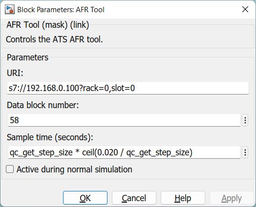
URI (tunable offline)
The URI identifying the PLC or simulation to which to connect. This parameter identifies the communication protocol and associated parameters. If the s7 protocol is used then it communicates with a PLC or the AFR Tool Simulation block. Otherwise it only communicates with a simulation based on the AFR Tool Simulation block.
For the s7 protocol, the URI takes the form:
s7://host?rack=R,slot=S
where the components are as follows:
|
Component |
Description |
|---|---|
|
host |
The hostname or IP address of the PLC eg. |
|
R |
The rack number of the PLC. The rack number is typically zero. |
|
S |
The slot number of the PLC. The slot number is typically zero. |
A typical s7 URI is: s7://192.168.0.100?rack=0,slot=0.
When interfacing to a simulation of the AFR tool, the tcpip protocol may also be used. For example: tcpip://localhost:18000. The hostname and port must match the hostname and port associated with the simulation (see the AFR Tool Simulation block).
Data block number (tunable offline)
The data block (DB) number of the memory in the PLC with which the block is communicating. This number is defined by the PLC program running on the PLC.
Sample time
The sample time of the block. A sample time of 0 indicates that the block will be treated as a continuous time block. A positive sample time indicates that the block is a discrete time block with the given sample time.
A sample time of -1 indicates that the block inherits its sample time.
The default sample time is set to qc_get_step_size * ceil(0.020 / qc_get_step_size)
which is an expression that returns the closest integer multiple of the fixed
step size of the model to 20 ms.
Active during normal simulation (tunable offline)
Indicates whether this block should communicate during normal simulation.
Targets
|
Target Name |
Compatible* |
Model Referencing |
Comments |
|---|---|---|---|
|
Yes |
Yes |
Only simulation is supported. |
|
|
Yes |
Yes |
Fully supported, including the s7 protocol. |
|
|
Yes |
Yes |
Only simulation is supported. |
|
|
Yes |
Yes |
Only simulation is supported. |
|
|
Yes |
Yes |
Only simulation is supported. |
|
|
Yes |
Yes |
Only simulation is supported. |
|
|
Yes |
Yes |
Only simulation is supported. |
|
|
Yes |
Yes |
Only simulation is supported. |
|
|
Yes |
Yes |
Only simulation is supported. |
|
|
Yes |
Yes |
Only simulation is supported. |
|
|
Yes |
Yes |
Only simulation is supported. |
|
|
Yes |
Yes |
Only simulation is supported. |
|
|
Yes |
Yes |
Only simulation is supported. |
|
|
Yes |
Yes |
Last fully supported in QUARC 2018. |
|
|
Rapid Simulation (RSIM) Target |
Yes |
Yes |
Only simulation is supported. |
|
S-Function Target |
No |
N/A |
Old technology. Use model referencing instead. |
|
Normal simulation |
Yes |
Yes |
Fully supported, including the s7 protocol. |
Copyright ©2026 Quanser Inc. This page was generated 2026-05-13. Submit feedback to Quanser about this page.
Link to this page.