
HIL Asynchronous Interrupt
Invokes a Function-Call Subsystem whenever the specified interrupts occur.
Library
QUARC Targets/Data Acquisition/Generic/Interrupts MATLAB Command Line Click to copy the following command line to the clipboard. Then paste it in the MATLAB Command Window: qc_open_library('quarc_library/Data Acquisition/Generic/Interrupts')
Description
The HIL Asynchronous Interrupt block invokes a Function-Call Subsystem whenever the specified interrupts associated with a data acquisition card occur. The Function-Call Subsystem is invoked asynchronously with respect to the sample time of the model. Hence, it may be called multiple times between sampling instants if one of the interrupts occurs more than once in that period.
If an interrupt has been detected on an interrupt source then the interrupt is automatically acknowledged by this block. Hence, the Function-Call Subsystem will only be invoked once each time an interrupt occurs.
The HIL Asynchronous Interrupt block supports two different modes: one-shot mode and repetitive mode. In either mode, the HIL Asynchronous Interrupt block creates a thread at model start. That thread then waits for an interrupt to occur before executing the Function Call Subsystem attached to the output from that thread.
In one-shot mode, the asychronous thread is signalled the first time the interrupt occurs only. The asynchronous thread wakes up, runs the Function Call Subsystem to completion and then exits. The asynchronous thread is not run repeatedly and has no associated sample rate. If the model is terminated prior to the completion of the asynchronous thread then the model will cancel the asynchronous thread and wait until the asynchronous thread completes before it exits.
In repetitive mode, the asychronous thread is signalled every time the interrupt occurs. For each occurrence of the interrupt, the asynchronous thread wakes up, runs the Function Call Subsystem and then waits for another occurrence of the interrupt. If the model is terminated prior to the completion of the asynchronous thread then the model will wait until the asynchronous thread completes before it exits. The asynchronous thread will complete as soon as the Function Call Subsystem has completed its execution. It will not wait for another interrupt from the HIL Asynchronous Interrupt block.
The repetitive mode is the default mode because it allows the Function Call Subsystem to be invoked every time the interrupt occurs. The one-shot mode is useful for calibration sequences in which the interrupt is only used the first time it occurs. For example, an encoder index pulse interrupt pulse may be used in this manner.
If the asynchronous thread is configured to have a lower priority than the base rate task of the model then the thread will be preempted when necessary by the base rate task and will not interfere with its execution. This mechanism allows event-driven operations that would be too slow to handle at the base rate to be handled in a separate thread instead. The priority of the base rate of the model is configured using the Minimum thread priority field of the QUARC tab of the Code Generation pane of the Configuration Parameters dialog.
Signals transferred between the asynchronous Function Call Subsystem and the periodic tasks of the model generally require one of the Protected RT or Unprotected RT rate transition blocks to ensure that data is transferred correctly between periodic and asynchronous tasks. More advanced techniques, such as FIFO queues, are available using the other blocks in the Asynchronous library.
In normal simulation the HIL Asynchronous Interrupt block does not spawn a separate thread because the Simulink engine does not support multiple threads. Instead, if the Active during normal simulation option is checked, it polls the interrupt and executes the Function Call Subsystem in the same thread as the rest of the simulation. Hence, the Function Call Subsystem will run to completion before the rest of the simulation continues. In real-time code, of course, the Function Call Subsystem is run concurrently with the periodic tasks in the diagram so this difference in behaviour must be taken into account when performing simulations.
Any number of HIL Asynchronous Interrupt blocks may be placed in the diagram, although it is more efficient to only use one. This block may not be placed in a referenced model because model referencing does not currently support asynchronous blocks.
Limitations
 Sinks blocks such as Display and Scope blocks are not
supported in external mode within asynchronous
subsystems like the Function Call Subsystem attached
to the HIL Asynchronous Interrupt block. In fact,
their presence can cause Simulink to crash in external mode.
This limitation is a characteristic of Simulink, not the generated code. To display the values of
signals from an asynchronous subsystem, use the FIFO Write
and FIFO Read blocks, or one of the Rate Transition
blocks such as the Protected RT
block, to transfer the signals to a periodic task and display their value from the
periodic task.
Sinks blocks such as Display and Scope blocks are not
supported in external mode within asynchronous
subsystems like the Function Call Subsystem attached
to the HIL Asynchronous Interrupt block. In fact,
their presence can cause Simulink to crash in external mode.
This limitation is a characteristic of Simulink, not the generated code. To display the values of
signals from an asynchronous subsystem, use the FIFO Write
and FIFO Read blocks, or one of the Rate Transition
blocks such as the Protected RT
block, to transfer the signals to a periodic task and display their value from the
periodic task.
Input Ports
This block has no input ports.
Output Ports
f()
A function-call output that should be connected to a Function-Call Subsystem. If multiple interrupt sources are specified then this output will be a vector in which each element corresponds to a single interrupt source. A Demux block may be used to invoke a separate Function-Call Subsystem for each interrupt source. If the vector output is connected to a single Function-Call Subsystem then the subsystem will be invoked if any of the interrupt sources occurs. A warning such as "Warning: The function-call subsystem 'mymodel/Function-Call Subsystem' has multiple asynchronous triggers specifying equal priorities. Set the Tasks with equal priority option in the Diagnostics page of the Configuration Parameters Dialog to "none" if tasks of equal priority can not preempt each other in the target system." will appear in the MATLAB Command Window, but can safely be ignored.
Parameters and Dialog Box
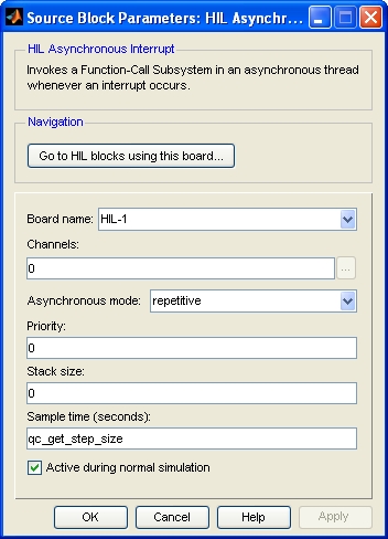
Board Name
The name of the board whose interrupt sources will be polled. Boards are configured using the HIL Initialize block. Place an HIL Initialize block in your diagram to add a board name to the list.
Channels (tunable offline)
The interrupt sources to read. The number of channels available depends on the board selected. Refer to Interrupt Channels for more information.
Select a board type from the list for board-specific details:
Asynchronous mode
Determines the semantics of the block. In one-shot mode the Function Call Subsystem is executed in a separate thread the first time the HIL Asynchronous Interrupt block is run. In repetitive mode the Function Call Subsystem is executed in a separate thread every time the HIL Asynchronous Interrupt block is run.
Priority (tunable offline)
The priority of the thread. In general, a value of 0 indicates the lowest priority and higher values indicate a higher priority. The number of priority levels available depends on the type of QUARC target for which code is being generated.
Stack size (tunable offline)
The stack size to use for the thread. Specifiy a value of 0 to use the default stack size for the QUARC target. The minimum stack size depends on the type of QUARC target for which code is being generated.
Sample time
The sample time of the block. A sample time of 0 indicates that the block will be treated as a continuous time block. A positive sample time indicates that the block is a discrete time block with the given sample time.
A sample time of -1 indicates that the block inherits its sample time. Since this is a source block, only inherent the sample time when it is placed in a conditionally executed subsystem, like a Triggered or Enabled Subsystem, or in a referenced model.
The default sample time is set to qc_get_step_size, which is a QUARC function that returns the fundamental sampling time of the model. Hence, the default sample time is a discrete sample time with the same sampling time as the fixed step size of the model.
Vector output
If this option is checked then the block will have a single vector output with one element in the vector for each channel. The states read from each channel will appear in the vector in the same order as the channels in the Channels parameter.
If this option is not checked then the block will have one output for each channel. The output ports will appear in the same order as the channels in the Channels parameter. Each port will be labeled with the corresponding channel number.
Targets
|
Target Name |
Compatible* |
Model Referencing |
Comments |
|---|---|---|---|
|
Yes |
Yes |
||
|
Yes |
Yes |
||
|
Yes |
Yes |
||
|
Yes |
Yes |
||
|
Yes |
Yes |
||
|
Yes |
Yes |
||
|
Yes |
Yes |
||
|
Yes |
Yes |
||
|
Yes |
Yes |
||
|
Yes |
Yes |
||
|
Yes |
Yes |
||
|
Yes |
Yes |
||
|
Yes |
Yes |
||
|
Yes |
Yes |
Last fully supported in QUARC 2018. |
|
|
Rapid Simulation (RSIM) Target |
Yes |
Yes |
|
|
S-Function Target |
No |
N/A |
Old technology. Use model referencing instead. |
|
Normal simulation |
Yes |
Yes |
Due to safety and liability concerns, the hardware may not be accessed during normal simulation. |
See Also
Copyright ©2026 Quanser Inc. This page was generated 2026-05-13. Submit feedback to Quanser about this page.
Link to this page.