
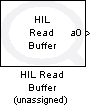
HIL Read Buffer
Reads the number of samples from a combination of input channels of a hardware-in-the-loop card at the specified rate.
Library
QUARC Targets/Data Acquisition/Generic/Buffered I/O MATLAB Command Line Click to copy the following command line to the clipboard. Then paste it in the MATLAB Command Window: qc_open_library('quarc_library/Data Acquisition/Generic/Buffered I//O')
Description
The HIL Read Buffer block reads the specified number of samples from a combination of input channels at the given sampling rate. The values read from these channels are output from the block after all the samples have been read. This block is more suited for data acquisition applications, rather than control, because it processes inputs in bulk rather than one sample at a time. If different types of channels are being read it is more efficient to use a single HIL Read Buffer block than multiple buffered I/O blocks specific to each type of channel.
The other outputs of the block will be assigned appropriate SI units, if possible. When the other outputs are a single vector then units are only assigned if every element would have the same units.
 All the channels which will be used as digital inputs must be entered
in the Digital input channels field of the
Digital Inputs pane in the HIL Initialize
block's parameters dialog. Doing so ensures that those channels will be configured as inputs when using a card for which
the digital I/O lines are programmable as inputs or outputs. Failure to configure these channels
in the Digital input channels field as inputs may result in the
HIL Read Buffer block failing to read those inputs.
All the channels which will be used as digital inputs must be entered
in the Digital input channels field of the
Digital Inputs pane in the HIL Initialize
block's parameters dialog. Doing so ensures that those channels will be configured as inputs when using a card for which
the digital I/O lines are programmable as inputs or outputs. Failure to configure these channels
in the Digital input channels field as inputs may result in the
HIL Read Buffer block failing to read those inputs.
Input Ports
This block has no input ports.
Output Ports
The number of output ports depends on the Frame-based output parameter. If this option is checked then there is one output for each type of channel (analog, encoder, digital or other) and each output is a frame containing the values read from the channels specified in the corresponding Channels parameter. Otherwise there is one output port for each channel and each port outputs the values read from the corresponding channel. Refer to the documentation on the Frame-based output parameter below for more details. Note that a license for the Signal Processing Blockset from The MathWorks is required in order to use frame-based outputs.
For vector outputs, the signal will have units commensurate with the corresponding channel. For frame-based outputs, the signal will only have units if all the channels corresponding to each element of the frame have the same units.
Data Type Support
The HIL Read Buffer block outputs real signals of type double
or the analog and other outputs. For encoder inputs, it
outputs signals of type int32, uint32
or double, and for digital inputs it outputs
signals of any of the standard Simulink data types. See the Signal Data Types pane
below for information on how the output data type is determined.
Parameters and Dialog Box
Individual Panes
Main Pane
The Main pane of the dialog appears as follows:
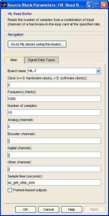
Board Name
The name of the board whose other channels will be read. Boards are configured using the HIL Initialize block. Place an HIL Initialize block in your diagram to add a board name to the list.
Clock
The clock to use as a basis for sampling the specified channels. In general, both system clocks and hardware clocks specific to the board are supported. This parameter must be a scalar. A positive value indicates a hardware clock. For example, enter 0 for HARDWARE_CLOCK_0, 1 for HARDWARE_CLOCK_1, etc. The number of hardware clocks available depends on the board selected. A negative value indicates a system clock. For example, enter -1 for SYSTEM_CLOCK_1, -2 for SYSTEM_CLOCK_2, etc. The sampling rate for the buffered operation is determined by the Frequency parameter. Refer to Clocks for more information.
Select a board type from the list for board-specific details:
Frequency
The frequency at which to sample the specified channels, in Hertz. Sampling of the channels is done by the driver for the board itself, not by the diagram. As the driver typically executes in kernel mode, this approach minimizes jitter in the samples.
Number of samples
The number of samples to read. One "sample" consists of all of the input channels. Hence, if there are three input channels and five samples requested, then fifteen measurements will be made, with three measurements made each of the five sampling instants.
Analog channels
The analog channels to read. The number of analog channels available depends on the board selected. Refer to Channels for more information.
Select a board type from the list for board-specific details:
Encoder channels
The encoder channels to read. The number of channels available depends on the board selected. Refer to Channels for more information.
Select a board type from the list for board-specific details:
Digital channels
The digital channels to read. The number of channels available depends on the board selected. Refer to Channels for more information.
Select a board type from the list for board-specific details:
Other channels
The other channels to read. The number of channels available depends on the board selected. Refer to Other Channels for more information about other channels in QUARC.
Most boards do not support other channels. Select a board type from the list for board-specific details:
Sample time
The sample time of the block. A sample time of 0 indicates that the block will be treated as a continuous time block. A positive sample time indicates that the block is a discrete time block with the given sample time.
A sample time of -1 indicates that the block inherits its sample time. Since this is a source block, only inherent the sample time when it is placed in a conditionally executed subsystem, like a Triggered or Enabled Subsystem, or in a referenced model.
The default sample time is set to qc_get_step_size, which is a QUARC function that returns the fundamental sampling time of the model. Hence, the default sample time is a discrete sample time with the same sampling time as the fixed step size of the model.
Frame-based output
If this option is checked then the block will have a single frame output for each type of channel (analog, encoder, digital and other) and for each frame there will be one row in the frame for each sample, and one column for each channel. The values read from each channel will appear in the frame in the same order as the channels in the corresponding Channels parameter. Note that a license for the Signal Processing Blockset from The MathWorks is required in order to use frame-based outputs.
If this option is not checked then the block will have one output for each channel. Each output will be a vector containing the measurements for that channel at each sampling instant. The output ports will appear in the same order as the channels in the Channels parameter. Each port will be labeled with the corresponding channel number and a prefix indicating the type of channel.
Port labels
This parameter allows the labels on the port to be changed to reflect the channel numbers or the signal names, when signal names are available. The table below enumerates the different display options. This parameter has no effect on generated code.
|
Option |
Description |
|---|---|
|
channel numbers |
Displays a letter from the table of prefixes above indicating the type of channel followed by the channel number. |
|
signal names |
Displays the full signal name for each port, if available. Otherwise the channel number is displayed. |
|
short names |
Displays a shortened version of the signal name for each port, if available. Otherwise the channel number is displayed. Each word in the signal name is typically shortened to no more than four characters. |
|
abbreviated names |
Displays an abbreviated version of the signal name for each port, if available. Otherwise the channel number is displayed. The abbreviated version is the first letter from each word in the signal name. Any parentheses or brackets are removed. |
Signal Data Types Pane
The Signal Data Types pane of the dialog appears as follows:
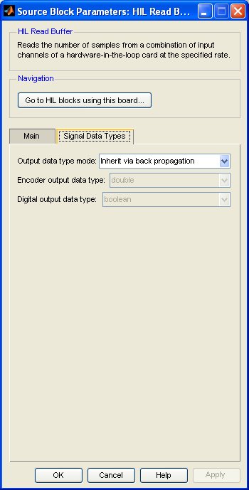
Output data type mode
Sets the data types of the outputs to be inherited by back propagation or to be specified explicitly in the dialog.
If back propagation is selected then the data types of the outputs will be determined
by the blocks to which the outputs are connected. If an output is not connected or
it is connected to a block which supports multiple datatypes, then the output data
type will be double.
Otherwise the data types of the outputs can be specified explicitly using the Encoder output data type and Digital output data type parameters.
Encoder output data type
Sets the data type of the encoder outputs explicitly.
Digital output data type
Sets the data type of the digital outputs explicitly.
Targets
|
Target Name |
Compatible* |
Model Referencing |
Comments |
|---|---|---|---|
|
Yes |
Yes |
||
|
Yes |
Yes |
||
|
Yes |
Yes |
||
|
Yes |
Yes |
||
|
Yes |
Yes |
||
|
Yes |
Yes |
||
|
Yes |
Yes |
||
|
Yes |
Yes |
||
|
Yes |
Yes |
||
|
Yes |
Yes |
||
|
Yes |
Yes |
||
|
Yes |
Yes |
||
|
No |
No |
Not currently supported. |
|
|
Yes |
Yes |
Last fully supported in QUARC 2018. |
|
|
Rapid Simulation (RSIM) Target |
Yes |
Yes |
|
|
S-Function Target |
No |
N/A |
Old technology. Use model referencing instead. |
|
Normal simulation |
Yes |
Yes |
Due to safety and liability concerns, the hardware may not be accessed during normal simulation. |
See Also
Copyright ©2026 Quanser Inc. This page was generated 2026-05-13. Submit feedback to Quanser about this page.
Link to this page.