
HIL Read Write
Reads and writes the specified channels immediately.
Library
QUARC Targets/Data Acquisition/Generic/Immediate I/O MATLAB Command Line Click to copy the following command line to the clipboard. Then paste it in the MATLAB Command Window: qc_open_library('quarc_library/Data Acquisition/Generic/Immediate I//O')
Description

The HIL Read Write block reads and writes the specified channels every time the block is executed. This block can be used with HIL boards that support simultaneous read and write operations. This block can read more than one type of channel at the same time and simultaneously write more than one type of channel at the same time. The channels are read and written immediately.
 Using this block in a feedback control loop will necessarily incur up to a one sample delay
between the inputs (read operation) and outputs (write operation) of the controller.
For example, consider a servo motor that uses encoder sensors and analog outputs to measure
the motor position and drive the motor.
Since this block executes a simultaneous read and write, the current sensor inputs (e.g.,
encoder reads) cannot be used to compute the current motor outputs (e.g., analog output
voltages) since the read-write operation is atomic; the motor voltages computed can only be
written on the following sampling instant. Therefore, up to a one sample delay
must be incurred in the feedback loop.
Using this block in a feedback control loop will necessarily incur up to a one sample delay
between the inputs (read operation) and outputs (write operation) of the controller.
For example, consider a servo motor that uses encoder sensors and analog outputs to measure
the motor position and drive the motor.
Since this block executes a simultaneous read and write, the current sensor inputs (e.g.,
encoder reads) cannot be used to compute the current motor outputs (e.g., analog output
voltages) since the read-write operation is atomic; the motor voltages computed can only be
written on the following sampling instant. Therefore, up to a one sample delay
must be incurred in the feedback loop.
Moreover, Simulink will not allow algebraic loops, so a delay (e.g., memory block, one sample delay) must be inserted if the outputs of this block are to be connected to the inputs of the block. To avoid this delay, use separate HIL Read and HIL Write blocks. This will ensure the inputs read will be used to compute the outputs written in the same sample period.
This block is useful for certain HIL boards that support simultaneous read-write operations but cannot accomplish two read-write operations within a sample period. This block can also be used in controllers where a one sample delay does not significantly affect the controller stability.
All the channels which will be used as digital inputs must be entered
in the Digital input channels field
of the Digital Inputs pane in the
HIL Initialize block's parameters dialog. Doing so
ensures that those channels will be configured as inputs when using a card for which the
digital I/O lines are programmable as inputs or outputs. Failure to configure these channels
in the Digital input channels field as inputs may result in the
HIL Read Write block failing to read those inputs.
Similarly, all the channels which will be used as digital outputs must be entered in the Digital output channels field of the Digital Outputs pane in the HIL Initialize block's parameters dialog. Doing so ensures that those channels will be configured as outputs when using a card for which the digital I/O lines are programmable as inputs or outputs. Failure to configure these channels in the Digital output channels field as outputs may result in the HIL Read Write block failing to write those outputs.
Input Ports
The number of input ports depends on the Vector inputs parameter. If this option is checked then there is one input port for each type of channel specified. Each of these inputs is a vector containing the measurements to write to the channels specified in the corresponding Channels parameter. The first input port will be for the analog channels, if used, the next port will be for the encoder channels, if used, etc.
Otherwise there is one input port for each channel and each port reads the value to write to the corresponding channel. The first set of input ports will be for the analog channels, if used, the next set of input ports will be for the encoder channels, if used, etc. Refer to the documentation on the Vector input parameter below for more details.
Output Ports
The number of output ports depends on the Vector outputs parameter. If this option is checked then there is one output port for each type of channel specified. Each of these outputs is a vector containing the measurements read from the channels specified in the corresponding Channels parameter. The first output port will be for the analog channels, if used, the next port will be for the encoder channels, if used, etc.
Otherwise there is one output port for each channel and each port outputs the measurement read from the corresponding channel. The first set of output ports will be for the analog channels, if used, the next set of output ports will be for the encoder channels, if used, etc. Refer to the documentation on the Vector output parameter below for more details.
Data Type Support
The HIL Read Write block input signals support any of the built-in Simulink datatypes except fixed point.
The HIL Read Write block outputs signals of type double for the analog and other channels, it outputs signals of
type int32or double for the encoder channels and it outputs any of the built-in Simulink datatypes except
fixed point for the digital channels. See the Signal Data Types pane below for information on how the output data
type is determined.
Parameters and Dialog Box
Individual Panes
Read channels Pane
The Read channels pane of the dialog appears as follows:
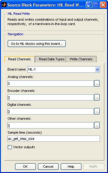
Board Name
The name of the board whose channels will be read. Boards are configured using the HIL Initialize block. Place an HIL Initialize block in your diagram to add a board name to the list.
Analog channels
The analog channels to read. The number of analog channels available depends on the board selected. Refer to Channels for more information. The output is the voltages read from the analog inputs.
Select a board type from the list for board-specific details:
Encoder channels
The encoder channels to read. The number of channels available depends on the board selected. Refer to Channels for more information. The output is the count values read from the encoder counters.
Select a board type from the list for board-specific details:
Digital channels
The digital channels to read. The number of channels available depends on the board selected. Refer to Channels for more information. The output is the states read from the digital inputs.
Select a board type from the list for board-specific details:
Other channels
The other channels to read. The number of channels available depends on the board selected. Refer to Other Channels for more information about other channels in QUARC. The output is the values read from the other inputs.
Most boards do not support other channels. Select a board type from the list for board-specific details:
Sample time
The sample time of the block. A sample time of 0 indicates that the block will be treated as a continuous time block. A positive sample time indicates that the block is a discrete time block with the given sample time.
A sample time of -1 indicates that the block inherits its sample time. Since this is a source block, only inherent the sample time when it is placed in a conditionally executed subsystem, like a Triggered or Enabled Subsystem, or in a referenced model.
The default sample time is set to qc_get_step_size, which is a QUARC function that returns the fundamental sampling time of the model. Hence, the default sample time is a discrete sample time with the same sampling time as the fixed step size of the model.
Vector outputs
If this option is checked then the block will have a vector output for each type of channel specified with one element in the vector for each channel of that type. The values read from each channel will appear in the vector in the same order as the channels in the corresponding Channels parameter. For example, if analog channels 3 and 4 are selected, then the first output port will be a 2-vector with the first element containing the voltages read from analog input 3 and the second element containing the voltages read from analog input 4. Each output port will be labeled with the prefix indicating the type of channel represented by that output port. Refer to the table below for an explanation of the prefixes used.
If this option is not checked then the block will have one output for each channel. The output ports will appear in the same order as the channels in the corresponding Channels parameter. Each port will be labeled with a prefix indicating the channel type and the corresponding channel number.The prefixes are:
|
|
|
|---|---|
|
|
analog |
|
|
encoder |
|
|
digital |
|
|
other |
Port labels
This parameter allows the labels on the port to be changed to reflect the channel numbers or the signal names, when signal names are available. The table below enumerates the different display options. This parameter has no effect on generated code.
|
Option |
Description |
|---|---|
|
channel numbers |
Displays a letter from the table of prefixes above or under the Write channels tab indicating the type of channel followed by the channel number. |
|
signal names |
Displays the full signal name for each port, if available. Otherwise the channel number is displayed. |
|
short names |
Displays a shortened version of the signal name for each port, if available. Otherwise the channel number is displayed. Each word in the signal name is typically shortened to no more than four characters. |
|
abbreviated names |
Displays an abbreviated version of the signal name for each port, if available. Otherwise the channel number is displayed. The abbreviated version is the first letter from each word in the signal name. Any parentheses or brackets are removed. |
Read Data Types Pane
The Read Data Types pane of the dialog appears as follows:
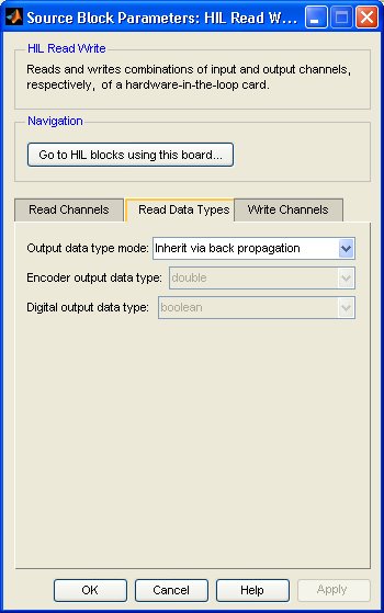
Output data type mode
Sets the data type of the output to be inherited by back propagation or to be specified
explicitly in the dialog. This parameter only affects the encoder and digital channels.
The analog and other channels are always double.
If back propagation is selected then the data type of the encoder and digital outputs
will be determined by the blocks to which these outputs are connected. If an encoder
output is not connected or it is connected to a block which supports multiple datatypes,
then the output data type will be double. If a digital
output is not connected or it is connected to a block which supports multiple datatypes,
then the output data type will be boolean.
Otherwise the data type of the encoder outputs can be specified explicitly using the Encoder output data type parameter and the data type of the digital outputs can be specified explicitly using the Digital output data type parameter.
Encoder output data type
Sets the data type of the encoder outputs explicitly.
Digital output data type
Sets the data type of the digital outputs explicitly.
Write channels Pane
The Write channels pane of the dialog appears as follows:
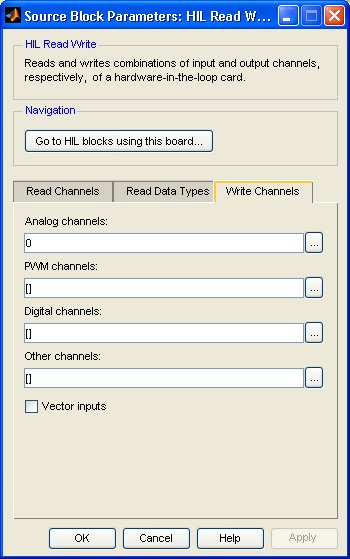
Analog channels
The analog channels to write. The number of analog channels available depends on the board selected. Refer to Channels for more information. The input is the voltages to write to the analog outputs.
Select a board type from the list for board-specific details:
PWM channels
The PWM channels to write. The number of channels available depends on the board selected. Refer to Channels for more information. The input is the duty cycles, frequencies or periods to write to the PWM outputs. The interpretation of the input depends on the PWM output mode set in the PWM output mode parameter of the HIL Initialize block.
Select a board type from the list for board-specific details:
Digital channels
The digital channels to write. The number of channels available depends on the board selected. Refer to Channels for more information. The input is the states to write to the digital outputs.
Select a board type from the list for board-specific details:
Other channels
The other channels to write. The number of channels available depends on the board selected. Refer to Other Channels for more information about other channels in QUARC. The input is the values to write to the other outputs.
Most boards do not support other channels. Select a board type from the list for board-specific details:
Vector inputs
If this option is checked then the block will have a vector input for each type of channel specified with one element in the vector for each channel of that type. The values written to each channel must appear in the vector in the same order as the channels in the corresponding Channels parameter. For example, if analog channels 3 and 4 are selected, then the first input port will be a 2-vector with the first element containing the voltages to write to analog output 3 and the second element containing the voltages to write to analog output 4. Each input port will be labeled with the prefix indicating the type of channel represented by that input port. Refer to the table below for an explanation of the prefixes used.
If this option is not checked then the block will have one input for each channel. The input ports will appear in the same order as the channels in the corresponding Channels parameter. Each port will be labeled with a prefix indicating the channel type and the corresponding channel number.The prefixes are:
|
|
|
|---|---|
|
|
analog |
|
|
PWM |
|
|
digital |
|
|
other |
Targets
|
Target Name |
Compatible* |
Model Referencing |
Comments |
|---|---|---|---|
|
Yes |
Yes |
||
|
Yes |
Yes |
||
|
Yes |
Yes |
||
|
Yes |
Yes |
||
|
Yes |
Yes |
||
|
Yes |
Yes |
||
|
Yes |
Yes |
||
|
Yes |
Yes |
||
|
Yes |
Yes |
||
|
Yes |
Yes |
||
|
Yes |
Yes |
||
|
Yes |
Yes |
||
|
Yes |
Yes |
Partially supported. Only the digital channels are supported. |
|
|
Yes |
Yes |
Last fully supported in QUARC 2018. |
|
|
Rapid Simulation (RSIM) Target |
Yes |
Yes |
|
|
S-Function Target |
No |
N/A |
Old technology. Use model referencing instead. |
|
Normal simulation |
Yes |
Yes |
Due to safety and liability concerns, the hardware may not be accessed during normal simulation. |
See Also
Copyright ©2026 Quanser Inc. This page was generated 2026-05-13. Submit feedback to Quanser about this page.
Link to this page.