
HIL Simulation
Allows a HIL board to be simulated.
Library
QUARC Targets/Data Acquisition/Generic/Configuration MATLAB Command Line Click to copy the following command line to the clipboard. Then paste it in the MATLAB Command Window: qc_open_library('quarc_library/Data Acquisition/Generic/Configuration')
Description

The HIL Simulation block allows a HIL board to be simulated. A model designed to use an actual HIL board, such as the Q2-USB, can be changed to access the simulated board just by adding a URI to the board identifier. Meanwhile, the simulated board is implemented in another model using the HIL Simulation block.
To use the HIL Simulation block, set the block parameters according to the number of channels of the various types. The HIL Simulation block will then provide inputs and outputs corresponding to those channels. The inputs to the block will be the values of the analog, encoder, digital and/or other input channels at the current sampling instant, and the outputs of the block will be the current analog, PWM, digital and/or other output values written by the model using the simulated card.
Also set the Universal Resource Identifier (URI) to indicate the communication channel on which the HIL Simulation block will listen for client connections, such as tcpip://localhost:18000. QUARC uses URI's for all its communications because it provides a uniform, extensible and flexible means of identifying the communication protocol to use and the associated communication parameters. Refer to Universal Resource Identifiers for more information.
The URI may be specified in the dialog parameters or via an input port. Which option is used is determined by the Source of URI parameter. When the URI is specified via an input, the input is typically driven by a Model Argument block, which allows a model argument to be used to assign the URI at runtime.
| If the URI is specified via an input port, the HIL Simulation block only samples the input when the model is first started. Hence, the URI cannot be changed while the model is running. |
The model wishing to use the simulated card simply adds the URI of the simulated card (specified in the URI on which to listen parameter of the HIL Simulation block) to the board identifier.
For example, suppose we have a model simulating Q2-USB board 0 using the HIL Simulation block and we wish to use TCP/IP to communicate between the model simulating the board and the model using the board. In this case, in the model simulating the card, we may set the URI on which to listen parameter to tcpip://localhost:18000 so that the TCP/IP protcol is used with port 18000. The Board type parameter will be q2_usb and the Board identifier parameter will be 0.
Meanwhile, in the model using the simulated card, we would change the board identifier from simply "0" to "0@tcpip://localhost:18000" (without the quotes). The model will now access the simulated card instead of an actual Q2-USB card.
Helpful Hints
Firewall
 If remote clients will be communicating with the HIL Simulation then be sure to configure the server machine's firewall
to allow incoming access on the port being used.
If remote clients will be communicating with the HIL Simulation then be sure to configure the server machine's firewall
to allow incoming access on the port being used.
Variable-size signals
When using the HIL Simulation block with variable-size signals in subsystems, make sure any
Action Port
MATLAB Command Line
Click to copy the following command line to the clipboard. Then paste it in the MATLAB Command Window:
doc ActionPort;,
Enable
MATLAB Command Line
Click to copy the following command line to the clipboard. Then paste it in the MATLAB Command Window:
doc Enable or
Trigger
MATLAB Command Line
Click to copy the following command line to the clipboard. Then paste it in the MATLAB Command Window:
doc Trigger ports are
configured to propagate the sizes of variable-size signals during execution. Refer to
Variable-Size Signals for more information
on variable-size signals.
Input Ports
a
A double vector of analog input voltages or currents. The length of this vector is determined by the Number of analog inputs parameter. The values written to this input port will appear as the analog voltages output by a HIL Read block in the model using the simulated board. If the number of analog inputs selected is zero then this port will not appear.
e
An int32 vector of encoder input counts. The length of this vector is determined by the Number of encoder inputs parameter. The values written to this input port will appear as the encoder counts output by a HIL Read block in the model using the simulated board. If the number of encoder inputs selected is zero then this port will not appear.
d
A boolean vector of digital input states. The length of this vector is determined by the Number of bidirectional digital I/O and Number of digital inputs only parameters. The values written to this input port will appear as the digital values output by a HIL Read block in the model using the simulated board. If the total number of digital inputs selected is zero then this port will not appear.
o
A double vector of other input values. The length of this vector is determined by the Other input channels parameter. The values written to this input port will appear as the other values output by a HIL Read block in the model using the simulated board. If no other inputs are selected then this port will not appear.
ip
An int32 vector of integer property values. The length of this vector is determined by the Integer property codes parameter under the Get Properties tab. The values written to this input port will appear as the property values output for integer properties by a HIL Get Property block in the model using the simulated board. If the integer property codes are an empty vector then this port will not appear.
dp
A vector of double property values. The length of this vector is determined by the Double property codes parameter under the Get Properties tab. The values written to this input port will appear as the property values output for double properties by a HIL Get Property block in the model using the simulated board. If the double property codes are an empty vector then this port will not appear.
sp<n>
A uint8 array of characters for string property <n>, where n is one of the property codes in the String property codes parameter under the Get Properties tab. The value written to this input port will appear as the property value output for string property n by a HIL Get Property block in the model using the simulated board. There is one port for each string property code. If the string property codes are an empty vector then these ports will not appear.
uri
A string specifying the URI upon which to listen and service client connections. The string
must be a null-terminated vector of characters represented as a vector of uint8 quantities.
It may be variable-sized. This string is typically provided either directly or indirectly by a
Model Argument
block or String Constant block.
This input is only available if the Source of URI parameter is
set to External input port. Refer to the documentation below on the
Source of URI parameter for details.
Output Ports
a
A double vector of analog output voltages or currents. The length of this vector is determined by the Number of analog outputs parameter. The values written to this output port come from the analog voltages input to a HIL Write block in the model using the simulated board. If the number of analog outputs selected is zero then this port will not appear.
p
A double vector of PWM output values. The length of this vector is determined by the Number of PWM outputs parameter. The values written to this output port come from the PWM values input to a HIL Write block in the model using the simulated board. If the number of PWM outputs selected is zero then this port will not appear.
d
A boolean vector of digital output states. The length of this vector is determined by the Number of bidirectional digital I/O and Number of digital outputs only parameters. The values written to this output port come from the digital values input to a HIL Write block in the model using the simulated board. If the total number of digital outputs selected is zero then this port will not appear.
o
A double vector of other output values. The length of this vector is determined by the Other output channels parameter. The values written to this output port come from the other values input to a HIL Write block in the model using the simulated board. If no other outputs are selected then this port will not appear.
ip
An int32 vector of integer property values. The length of this vector is determined by the Integer property codes parameter under the Set Properties tab. The values produced at this output port are set to the values from the Initial integer properties parameter at model start. The output will then take on the integer values set via a HIL Set Property block in the model using the simulated board. If the integer property codes are an empty vector then this port will not appear.
dp
A vector of double property values. The length of this vector is determined by the Double property codes parameter under the Set Properties tab. The values produced at this output port are set to the values from the Initial double properties parameter at model start. The output will then take on the double values set via a HIL Set Property block in the model using the simulated board. If the double property codes are an empty vector then this port will not appear.
sp<n>
A uint8 array of characters for string property <n>, where n is one of the property codes in the String property codes parameter under the Set Properties tab. The values produced at this output port are set to the values from the Initial string properties parameter at model start. The output will then take on the string value set via a HIL Set Property block in the model using the simulated board. If the string property codes are an empty vector then this port will not appear.
...
A separate port is added for each board-specific option specified in the Board-specific options template. The data type of the port will match the data type of the associated option. The port will be labelled with the name of the board-specific option.
con
An optional port showing the number of clients currently connected to the simulation. This port is only available when the Show number of client connections parameter is checked.
Parameters and Dialog Box
Common Buttons
The dialog box for the HIL Simulation block contains the usual , and buttons for agreeing to the changes, cancelling the changes and getting help respectively.
Individual Panes
Main Pane
The Main pane of the dialog appears as follows:
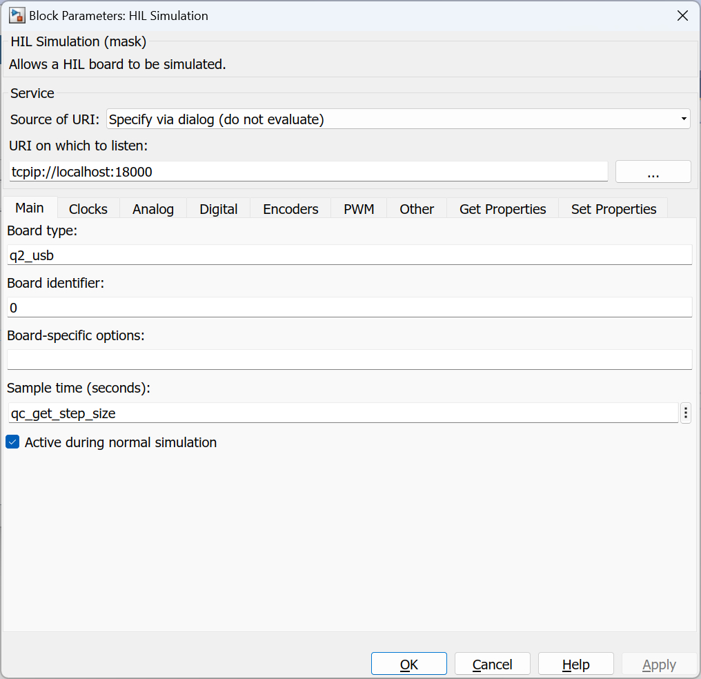
Source of URI
Indicates whether the URI should be determined from the dialog parameters or an
input port. If this field is set to Specify via dialog (do not evaluate) then
the URI is specified via the URI upon which to listen
parameter. In this case, the URI is not evaluated as a MATLAB expression but is
interpreted as a literal string. However, format specifiers are recognized. Refer
to qc_perform_substitutions
for a list of the format specifiers available.
 If format specifiers which change frequently, such as '%{time}' or
'%{instance}', are used in the URI then the HIL Simulation block cannot be placed
in a referenced model, because the URI will change from the time the code is built to when
the code is run. As a result, Simulink will insist that the code be rebuilt because block
parameters in referenced models are inlined. Instead, specify the source of the URI as
If format specifiers which change frequently, such as '%{time}' or
'%{instance}', are used in the URI then the HIL Simulation block cannot be placed
in a referenced model, because the URI will change from the time the code is built to when
the code is run. As a result, Simulink will insist that the code be rebuilt because block
parameters in referenced models are inlined. Instead, specify the source of the URI as
External input port and pass the URI from the top-level model. Use a
String Constant block
in the top-level model to generate the URI.
If this field is set to Specify via dialog (evaluate) then the URI is also specified
via the URI upon which to listen parameter. However, in this case,
the URI is evaluated as a MATLAB expression. This option is convenient for using a variable
in the MATLAB workspace for the URI.
If this field is set to External input port then the URI upon which to listen
parameter is ignored and an extra input port is provided which determines the URI.
URI on which to listen
The URI on which to listen for clients using the simulated board. Note that the URI
must be unique for each simulated board. This parameter identifies the communication protocol
and associated parameters. For example, a URI of tcpip://localhost:18000
will cause the HIL Simulation block to use TCP/IP and listen for connections on port
18000. This field is only used if the Source of URI
parameter is set to Specify via dialog (do not evaluate) or Specify via dialog (evaluate).
Refer to Universal Resource Identifiers for
more information about URIs and the communications protocols supported by QUARC.
Board type
The type of HIL board being simulated. For example, for the Q2-USB board the board type is q2_usb. Make sure this matches a board type in the HIL Initialize block.
Board identifier
The identifier of the board. This parameter is used to differentiate between boards when there is more than one board of the given type being simulated. Typically, this parameter is 0, indicating the first board of the given type. Subsequent boards are numbered sequentially. Hence, the second board in the system is board 1. Some board types support the use of a device name as the board identifier, such as "Dev1", instead of a board number.
Board-specific options
The board-specific options for the board as a template. The template takes the form:
<name>=<format>;<name>=<format>...
The <name > is the name of the option. The <format> is a format specifier identifying the data type of the option and any restrictions upon its value. The format specifier always starts with a percent sign, %, and is followed by the type. Valid types are shown in the table below:
|
Formt Specifier |
Description |
|---|---|
|
%b |
Indicates that the option takes a boolean value, which may be "0", "f", "false", "n", "no", or "off", or "1", "t", "true", "on", "y" or "yes". |
|
%d |
Indicates that the option takes an integer value. Integer values may be specified in decimal, octal or hexadecimal format. Octal values are prefixed with a "0" and hexadecimal values with "0x". |
|
%f |
Indicates that the option takes a real (floating-point) value. |
|
%t |
Indicates that the option takes a timeout value, which is a positive real value. |
The format specifier may be followed by a range or enumeration restriction. A range restriction takes the form:
[<min>,<max>]
where <min> is the minimum value allowed and <max> is the maximum value allowed. The minimum and maximum values must be specified using the same data type as indicated by the format specifier. The option may take on any value between the minimum and maximum, inclusive.
An enumeration restriction forces the option to take a value from a finite set of possibilities. If the possibilities are expressed in the form:
(<value1>|<value2>|...|<valueN>)
then the option may take any of the values given in the enumeration. Each <value> must have the same data type as indicated by the format specified.
If the possibilities are expressed in the form:
(<name1>|<name2>|...|<nameN>)
then the option may be assigned to any one of the names in the enumeration. The value output from the block for the option will be the zero-based index of the name in the list. For example, <name1> will produce a value of zero, <name2> will produce a value of one, etc.
Finally, if the possibilities are expressed in the form:
(<name1>=<value1>|<name2>=<value2>|...|<nameN>=<valueN>)
then the option may be assigned to any one of the names in the enumeration. The value output from the block for the option will be the value assigned to that name in the list. For example, <name1> will produce a value of <value1>, <name2> will produce a value of <value2>, etc.
The following table shows some examples of board-specific option templates:
|
Template |
Description |
Sample Values for Option |
|---|---|---|
|
%b |
Unrestricted boolean value. |
false, true, on, off |
|
%d |
Unrestricted integer value. |
-1234, 0xabcd, 077, 65 |
|
%d[5,10] |
Integer value restricted to lie between 5 and 10 inclusive. |
5, 6, 8, 10 |
|
%d(5|7|9) |
Integer value restricted to be 5, 7 or 9. |
5, 7, 9 |
|
%d(low|medium|high) |
Integer value accessed by name where low=0, medium=1 and high=2. |
low, medium or high |
|
%d(low=2|medium=3|high=4) |
Integer value accessed by name where low=2, medium=3 and high=4. |
low, medium or high |
|
%f |
Unrestricted floating-point value. |
3.14, -1.2e34, 72e-6 |
|
%f[5,10] |
Floating-point value restricted to lie between 5 and 10 inclusive. |
5, 6.7, 8.2, 10 |
|
%f(3.14|2.82|1.5) |
Floating-point value restricted to be 3.14, 2.82 or 1.5. |
3.14, 2.82, 1.5 |
|
%f(low|medium|high) |
Floating-point value accessed by name where low=0, medium=1 and high=2. |
low, medium or high |
|
%f(pi=3.14|e=2.82|rational=1.5) |
Floating-point value accessed by name where pi=3.14, e=2.82 and rational=1.5. |
pi, e or rational |
|
%t |
Unrestricted timeout value. |
1.5, 100, 0.15 |
Timeouts and boolean values may also use ranges or enumerations. These were simply not shown in the examples. As a final example:
gyro_fs=%d(1000|2000|4000);acc_fs=%d(1|2|4|8|16);max_speed=%f;delay=%t;use_pwm=%b
which shows five board-specific options: gyro_fs, acc_fs, max_speed, delay and use_pwm. The gyro_fs option may be assigned an integer value of 1000, 2000 or 4000. The acc_fs option may be assigned an integer value of 1, 2, 4, 8 or 16. The max_speed may be any real number, and finally the delay may be a timeout value, which is a positive real number. The use_pwm option may be a boolean value. This board-specific options parameter value results in five additional outputs from the HIL Simulation block: two int32 outputs, two double outputs and a logical output.
When the HIL Simulation block processes board-specific options it currently ignores any options it receives that are not specified in the template. That way it is only necessary to specific the board-specific options in which you are interested when simulating a card, rather than all of them. Also, if the field is empty then all board-specific options set by the application using the simulated card will be ignored.
Sample time
The sample time of the block. A sample time of 0 indicates that the block will be treated as a continuous time block. A positive sample time indicates that the block is a discrete time block with the given sample time.
A sample time of -1 indicates that the block inherits its sample time from the input. The sample time must be inherited when the block is placed in a conditionally executed subsystem like the Triggered Subsystem block.
To set the sample time to the fundamental sampling time of the model, use the qc_get_step_size function, which is a QUARC function that returns the fundamental sampling time of the model. The fundamental sampling time of the model is the sampling time entered in the Fixed step size field of the Solver pane of the Configuration parameters.
Active during normal simulation
Indicates whether this block should simulate the board during normal simulation. If the HIL Simulation block is deactivated by unchecking this option then the simulated board will not be accessible.
Show number of client connections
Check this option to add an extra output port showing the number of clients currently connected to the simulation.
Clocks Pane
The Clocks pane of the dialog appears as follows:
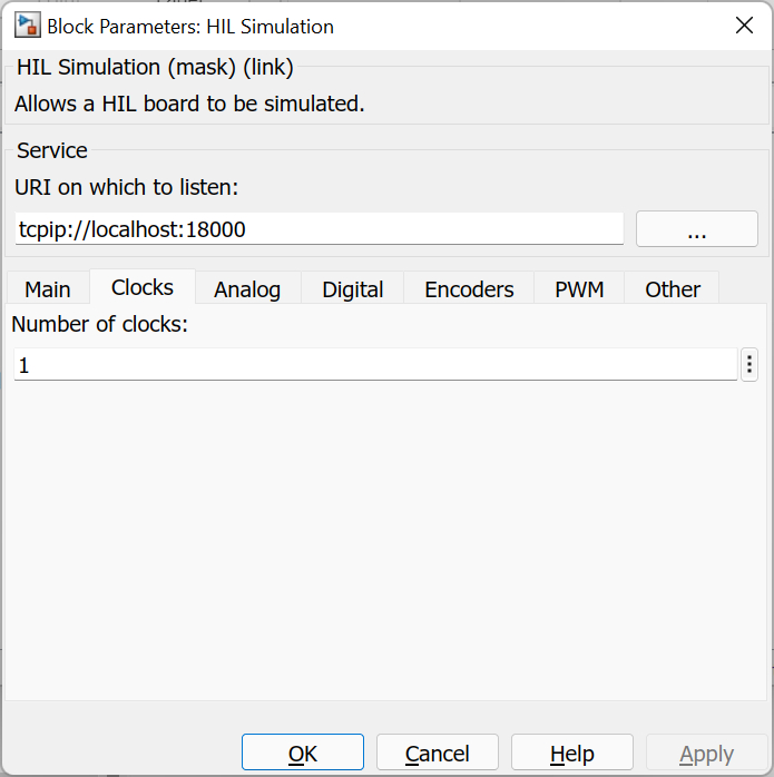
Number of clocks
The number of hardware clocks supported by the simulated card. This parameter must be an integer scalar.
Analog Pane
The Analog pane of the dialog appears as follows:
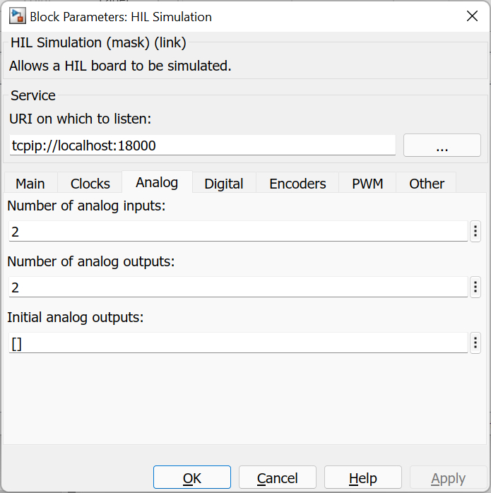
Number of analog inputs
The number of analog input channels supported by the simulated card. This parameter must be an integer scalar.
Number of analog outputs
The number of analog output channels supported by the simulated card. This parameter must be an integer scalar.
Initial analog outputs
The value(s) to output on the analog output channels when the model starts. This parameter may be a vector or scalar. If this parameter has fewer elements than specified in the Number of analog outputs parameter then the value of the last element will be used for the rest of the analog output channels.
Digital Pane
The Digital pane of the dialog appears as follows:
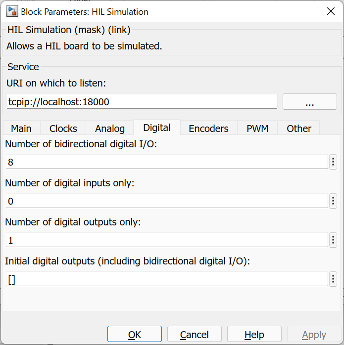
Number of bidirectional digital I/O
The number of digital channels supported by the simulated card which are bidirectional. The bidirectional digital channels will be numbered from zero. The bidirectional channels can be used as inputs or outputs. This parameter must be an integer scalar.
Number of digital inputs only
The number of digital channels supported by the simulated card which are strictly inputs. The digital input only channels will be numbered following the bidirectional digital I/O channels. Note that digital input only channel numbers may overlap with digital output only channel numbers. This parameter must be an integer scalar.
Number of digital outputs only
The number of digital channels supported by the simulated card which are strictly outputs. The digital output only channels will be numbered following the bidirectional digital I/O channels. Note that digital input only channel numbers may overlap with digital output only channel numbers. This parameter must be an integer scalar.
Initial digital outputs
The value(s) to output on the digital output channels when the model starts. This parameter may be a vector or scalar. If this parameter has fewer elements than specified in the Number of bidirectional digital I/O parameter plus the Number of digital outputs only parameter then the value of the last element will be used for the rest of the digital output channels. The first elements in the vector correspond to the digital I/O channels and the remaining elements to the channels that are digital outputs only.
Encoders Pane
The Encoders pane of the dialog appears as follows:
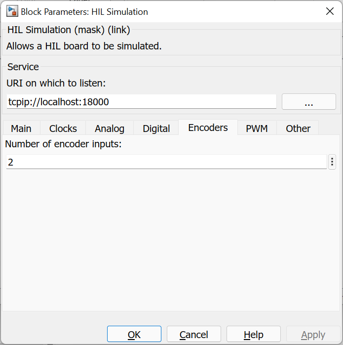
Number of encoder inputs
The number of encoder input channels supported by the simulated card. This parameter must be an integer scalar.
PWM Pane
The PWM pane of the dialog appears as follows:
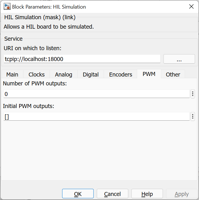
Number of PWM outputs
The number of PWM output channels supported by the simulated card. This parameter must be an integer scalar.
Initial PWM outputs
The value(s) to output on the PWM output channels when the model starts. This parameter may be a vector or scalar. If this parameter has fewer elements than specified in the Number of PWM outputs parameter then the value of the last element will be used for the rest of the PWM output channels.
Other Pane
The Other pane of the dialog appears as follows:
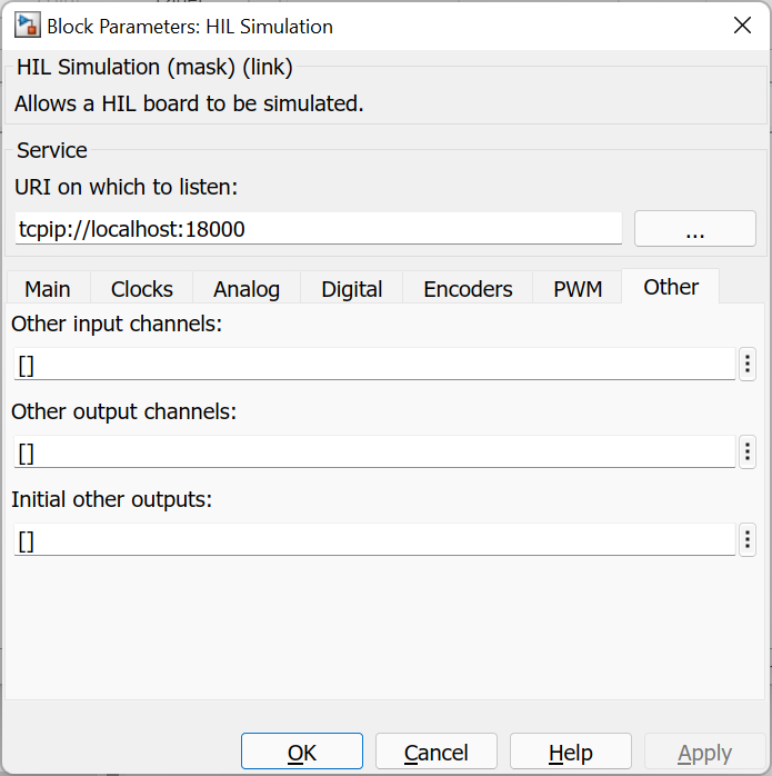
Other input channels
The other input channels supported by the card. This parameter may be a scalar or vector containing the channel numbers of the other input channels. Unlike other channel types, other channels are not numbered sequentially but according to purpose, so supplying the number of other input channels is not enough to simulate these channels. The input to the block for other input channels will be a vector of the same size as this parameter, and each element will correspond to the other input channel at the same index position. Refer to Channels for general information about other channels in QUARC.
Other output channels
The other output channels supported by the card. This parameter may be a scalar or vector containing the channel numbers of the other output channels. Unlike other channel types, other channels are not numbered sequentially but according to purpose, so supplying the number of other output channels is not enough to simulate these channels. The output from the block for other output channels will be a vector of the same size as this parameter, and each element will correspond to the other output channel at the same index position. Refer to Channels for general information about other channels in QUARC.
Initial other outputs
The value(s) to output on the other output channels when the model starts. This parameter may be a vector or scalar. If this parameter has fewer elements than the Other output channels parameter then the value of the last element will be used for the rest of the other output channels.
Get Properties Pane
The Get Properties pane of the dialog appears as follows:
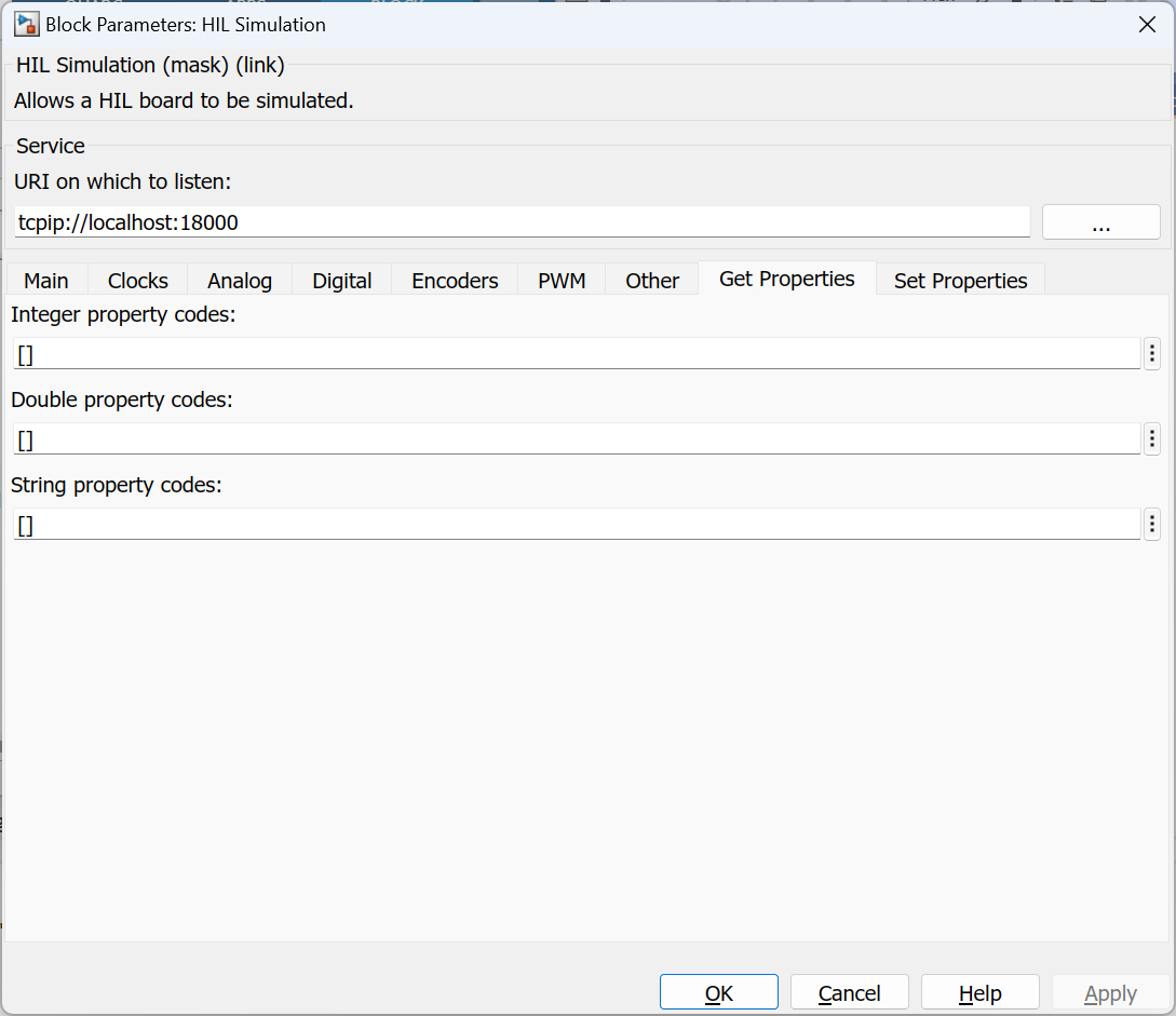
Integer property codes
The integer properties that may be read from the card. This parameter may be a scalar or vector containing the property codes of the integer properties. Integer properties are not necessarily numbered sequentially, so supplying the number of integer properties is not enough to simulate these properties. The input to the block for integer properties will be a vector of the same size as this parameter, and each element will correspond to the integer property code at the same index position. This parameter may be an empty matrix, [].
Double property codes
The double properties that may be read from the card. This parameter may be a scalar or vector containing the property codes of the double properties. Double properties are not necessarily numbered sequentially, so supplying the number of double properties is not enough to simulate these properties. The input to the block for double properties will be a vector of the same size as this parameter, and each element will correspond to the double property code at the same index position. This parameter may be an empty matrix, [].
String property codes
The string properties that may be read from the card. This parameter may be a scalar or vector containing the property codes of the string properties. String properties are not necessarily numbered sequentially, so supplying the number of string properties is not enough to simulate these properties. There will be a separate input to the block for each string property code listed. This parameter may be an empty matrix, [].
Set Properties Pane
The Set Properties pane of the dialog appears as follows:
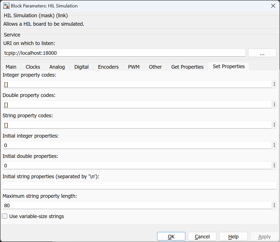
Integer property codes
The integer properties that may be written to the card. This parameter may be a scalar or vector containing the property codes of the integer properties. Integer properties are not necessarily numbered sequentially, so supplying the number of integer properties is not enough to simulate these properties. The output from the block for integer properties will be a vector of the same size as this parameter, and each element will correspond to the integer property code at the same index position. This parameter may be an empty matrix, [].
Double property codes
The double properties that may be written to the card. This parameter may be a scalar or vector containing the property codes of the double properties. Double properties are not necessarily numbered sequentially, so supplying the number of double properties is not enough to simulate these properties. The output from the block for double properties will be a vector of the same size as this parameter, and each element will correspond to the double property code at the same index position. This parameter may be an empty matrix, [].
String property codes
The string properties that may be written to the card. This parameter may be a scalar or vector containing the property codes of the string properties. String properties are not necessarily numbered sequentially, so supplying the number of string properties is not enough to simulate these properties. There will be a separate output from the block for each string property code listed. This parameter may be an empty matrix, [].
Initial integer properties
The value(s) to output for the integer properties when the model starts. This parameter may be a vector or scalar. If this parameter has fewer elements than the Integer property codes parameter on this tab then the value of the last element will be used for the rest of the integer properties.
Initial doouble properties
The value(s) to output for the double properties when the model starts. This parameter may be a vector or scalar. If this parameter has fewer elements than the Double property codes parameter on this tab then the value of the last element will be used for the rest of the double properties.
Initial string properties
The value(s) to output for the string properties when the model starts. This parameter is not evaluated but
is treated as a string. The backslash will be treated as an escape character so the sequence \n
will be treated as a newline character. Newline characters separate string properties.
Maximum string property length
The maximum size allowed for string properties. The string property outputs will use this value as their maximum width.
Use variable-size strings
If this option is checked then the string property outputs will be variable-size signals. Otherwise they will be fixed-size signals.
Targets
|
Target Name |
Compatible* |
Model Referencing |
Comments |
|---|---|---|---|
|
Yes |
Yes |
||
|
Yes |
Yes |
||
|
Yes |
Yes |
||
|
Yes |
Yes |
||
|
Yes |
Yes |
||
|
Yes |
Yes |
||
|
Yes |
Yes |
||
|
Yes |
Yes |
||
|
Yes |
Yes |
||
|
Yes |
Yes |
||
|
Yes |
Yes |
||
|
Yes |
Yes |
||
|
Yes |
Yes |
||
|
Yes |
Yes |
Last fully supported in QUARC 2018. |
|
|
Rapid Simulation (RSIM) Target |
Yes |
Yes |
|
|
S-Function Target |
No |
N/A |
Old technology. Use model referencing instead. |
|
Normal simulation |
Yes |
Yes |
See Also
Copyright ©2026 Quanser Inc. This page was generated 2026-05-13. Submit feedback to Quanser about this page.
Link to this page.