
HIL Write Analog
Writes the specified analog channels immediately.
Library
QUARC Targets/Data Acquisition/Generic/Immediate I/O MATLAB Command Line Click to copy the following command line to the clipboard. Then paste it in the MATLAB Command Window: qc_open_library('quarc_library/Data Acquisition/Generic/Immediate I//O')
Description

The HIL Write Analog block writes the specified analog channels every time the block is executed. The channels are written immediately.
Input Ports
The number of input ports depends on the Vector input parameter. If this option is checked then the input is a vector containing the analog voltages to write to the channels specified in the Channels parameter. Otherwise there is one input port for each channel and each port contains the analog voltage to write to the corresponding channel. Refer to the documentation on the Vector input parameter below for more details.
Output Ports
This block has no output ports.
Data Type Support
The HIL Write Analog block accepts signals of any of the built-in Simulink data types. Fixed point is not supported.
Parameters and Dialog Box
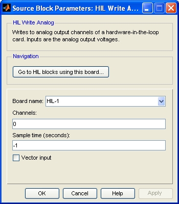
Board Name
The name of the board whose analog channels will be written. Boards are configured using the HIL Initialize block. Place an HIL Initialize block in your diagram to add a board name to the list.
Channels
The analog channels to write. The number of channels available depends on the board selected. Refer to Channels for more information.
Select a board type from the list for board-specific details:
Sample time
The sample time of the block. A sample time of 0 indicates that the block will be treated as a continuous time block. A positive sample time indicates that the block is a discrete time block with the given sample time.
A sample time of -1 indicates that the block inherits its sample time from the input. The block inherits the sample time by default.
To set the sample time to the fundamental sampling time of the model, use the qc_get_step_size function, which is a QUARC function that returns the fundamental sampling time of the model. The fundamental sampling time of the model is the sampling time entered in the Fixed step size field of the Solver pane of the Configuration parameters.
Vector input
If this option is checked then the block will have a single vector input with one element in the vector for each channel. The voltages for each channel should appear in the vector in the same order as the channels in the Channels parameter.
If this option is not checked then the block will have one input for each channel. The input ports will appear in the same order as the channels in the Channels parameter. Each port will be labeled with the corresponding channel number.
Port labels
This parameter allows the labels on the port to be changed to reflect the channel numbers or the signal names, when signal names are available. The table below enumerates the different display options. This parameter has no effect on generated code.
|
Option |
Description |
|---|---|
|
channel numbers |
Displays the channel number. |
|
signal names |
Displays the full signal name for each port, if available. Otherwise the channel number is displayed. |
|
short names |
Displays a shortened version of the signal name for each port, if available. Otherwise the channel number is displayed. Each word in the signal name is typically shortened to no more than four characters. |
|
abbreviated names |
Displays an abbreviated version of the signal name for each port, if available. Otherwise the channel number is displayed. The abbreviated version is the first letter from each word in the signal name. Any parentheses or brackets are removed. |
Targets
|
Target Name |
Compatible* |
Model Referencing |
Comments |
|---|---|---|---|
|
Yes |
Yes |
||
|
Yes |
Yes |
||
|
Yes |
Yes |
||
|
Yes |
Yes |
||
|
Yes |
Yes |
||
|
Yes |
Yes |
||
|
Yes |
Yes |
||
|
Yes |
Yes |
||
|
Yes |
Yes |
||
|
Yes |
Yes |
||
|
Yes |
Yes |
||
|
Yes |
Yes |
||
|
No |
No |
Not supported. |
|
|
Yes |
Yes |
Last fully supported in QUARC 2018. |
|
|
Rapid Simulation (RSIM) Target |
Yes |
Yes |
|
|
S-Function Target |
No |
N/A |
Old technology. Use model referencing instead. |
|
Normal simulation |
Yes |
Yes |
Due to safety and liability concerns, the hardware may not be accessed during normal simulation. |
See Also
Copyright ©2026 Quanser Inc. This page was generated 2026-05-13. Submit feedback to Quanser about this page.
Link to this page.