
HIL Write Timebase
Writes to the specified channels at the sampling rate of the model and acts as a timebase for the model.
Library
QUARC Targets/Data Acquisition/Generic/Timebases MATLAB Command Line Click to copy the following command line to the clipboard. Then paste it in the MATLAB Command Window: qc_open_library('quarc_library/Data Acquisition/Generic/Timebases')
Description
The HIL Write Timebase block writes to the specified channels at every sampling instant. The timebase for the model is provided by the block itself. Only one HIL Timebase block may appear in the model. Multiple timebases for a model are not supported. This block can write to more than one type of channel at the same time. Using this block is more efficient than using separate blocks for each channel type when more than one type of channel is being written.
The other inputs of the block will be assigned appropriate SI units, if possible. When the other inputs are a single vector then units are only assigned if every element would have the same units.
 All the channels which will be used as digital outputs must be entered
in the Digital output channels
field of the Digital Outputs pane in the
HIL Initialize block's parameters dialog. Doing so ensures
that those channels will be configured as outputs when using a card for which the
digital I/O lines are programmable as inputs or outputs. Failure to configure these channels
in the Digital output channels field as outputs may result in the
HIL Write Timebase block failing to write those outputs.
All the channels which will be used as digital outputs must be entered
in the Digital output channels
field of the Digital Outputs pane in the
HIL Initialize block's parameters dialog. Doing so ensures
that those channels will be configured as outputs when using a card for which the
digital I/O lines are programmable as inputs or outputs. Failure to configure these channels
in the Digital output channels field as outputs may result in the
HIL Write Timebase block failing to write those outputs.
Limitations
Data streaming not control
The HIL Write Timebase block is not intended for control.
The HIL Write Timebase blocks maintain an internal buffer whose size is set by the Samples in buffer parameter. Each time the block executes, the input signal is written to this buffer. In the background, the data in the buffer is written to the hardware at the sampling rate of the model, with one sample written each period. The HIL Write Timebase blocks do not wait for each sample to be written to the hardware. They only wait for space in the buffer. For example, if the buffer has room for 10 samples, then the model will quickly execute 10 iterations, filling up the buffer. Once the buffer is full, the model will wait for the next sampling instant for the oldest sample to be written to the hardware and to make room for another sample. Hence, after those initial 10 iterations the model will run at the sampling rate expected. However, the data written to the hardware will lag the current value of the input signal by 10 iterations!
Thus, the HIL Write Timebase blocks are unsuitable for control, because
lags are generally destabilizing. Instead, they are intended for data streaming applications, such as
audio, where constant lags are often acceptable.
For control systems, use one of the HIL Read Timebase blocks to establish the
sampling rate instead and use one of the HIL Write immediate I/O blocks to write
to the hardware.
Helpful Hints
Using ESCs
 For producing outputs compatible with electronic speed controllers (ESCs), the
ESC Output block may be used to
convert a throttle value to a PWM output value.
For producing outputs compatible with electronic speed controllers (ESCs), the
ESC Output block may be used to
convert a throttle value to a PWM output value.
Input Ports
The number of input ports depends on the Vector inputs parameter. If this option is checked then there is one input port for each type of channel specified. Each of these inputs is a vector containing the measurements to write to the channels specified in the corresponding Channels parameter. The first input port will be for the analog channels, if used, the next port will be for the encoder channels, if used, etc.
Otherwise there is one input port for each channel and each port reads the value to write to the corresponding channel. The first set of input ports will be for the analog channels, if used, the next set of input ports will be for the encoder channels, if used, etc. Refer to the documentation on the Vector input parameter below for more details.
For scalar inputs, the signal will have units commensurate with the corresponding channel. For vector inputs, the signal will only have units if all the channels corresponding to each element of the vector have the same units.
Output Ports
This block has no output ports.
Data Type Support
The HIL Read Timebase block supports any of the built-in Simulink datatypes except fixed point.
Parameters and Dialog Box
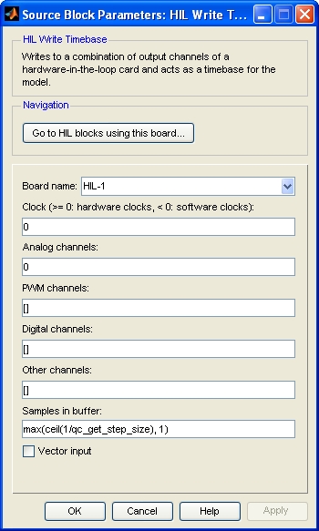
Board Name
The name of the board whose channels will be written. Boards are configured using the HIL Initialize block. Place an HIL Initialize block in your diagram to add a board name to the list.
Clock
The clock to use as a basis for the timebase. In general, both system clocks and hardware clocks specific to the board are supported. This parameter must be a scalar. A positive value indicates a hardware clock. For example, enter 0 for HARDWARE_CLOCK_0, 1 for HARDWARE_CLOCK_1, etc. The number of hardware clocks available depends on the board selected. A negative value indicates a system clock. For example, enter -1 for SYSTEM_CLOCK_1, -2 for SYSTEM_CLOCK_2, etc. The sampling rate for the block is determined by the fundamental sampling rate of the model, which is the sampling time entered in the Fixed step size field of the Solver pane of the Configuration parameters. Refer to Clocks for more information.
Select a board type from the list for board-specific details:
Analog channels
The analog channels to write. The number of analog channels available depends on the board selected. Refer to Channels for more information. The input is the voltages to write to the analog outputs.
Select a board type from the list for board-specific details:
PWM channels
The PWM channels to write. The number of channels available depends on the board selected. Refer to Channels for more information. The input is the duty cycles, frequencies or periods to write to the PWM outputs. The interpretation of the input depends on the PWM output mode set in the PWM output mode parameter of the HIL Initialize block.
Select a board type from the list for board-specific details:
Digital channels
The digital channels to write. The number of channels available depends on the board selected. Refer to Channels for more information. The input is the states to write to the digital outputs.
Select a board type from the list for board-specific details:
Other channels
The other channels to write. The number of channels available depends on the board selected. Refer to Other Channels for more information about other channels in QUARC. The output is the values to write to the other outputs.
Most boards do not support other channels. Select a board type from the list for board-specific details:
Samples in buffer
The number of samples in the task buffer. Timebase blocks are implemented as HIL tasks. Tasks operate as separate "threads" in the driver for the card that read data from the hardware at a given rate. The data read is stored in the task buffer. If the task buffer overflows then the blocks stops the model with an error. Each time the block executes, it reads one sample from the task buffer. If there is no data in the task buffer then it waits until a sample arrives. Hence, the block synchronizes the diagram to the sampling rate of the task. Making the number of samples in the task buffer greater than one allows the sampling rate to temporarily exceed one sampling interval, which is useful for normal simulation.
Some boards restrict the number of samples that may be specified. Select a board type from the list for board-specific details:
Vector input
If this option is checked then the block will have a vector input for each type of channel specified with one element in the vector for each channel of that type. The values written to each channel must appear in the vector in the same order as the channels in the corresponding Channels parameter. For example, if analog channels 3 and 4 are selected, then the first input port will be a 2-vector with the first element containing the voltages to write to analog output 3 and the second element containing the voltages to write to analog output 4. Each input port will be labeled with the prefix indicating the type of channel represented by that input port. Refer to the table below for an explanation of the prefixes used.
If this option is not checked then the block will have one input for each channel. The input ports will appear in the same order as the channels in the corresponding Channels parameter. Each port will be labeled with a prefix indicating the channel type and the corresponding channel number.The prefixes are:
|
|
|
|---|---|
|
|
analog |
|
|
PWM |
|
|
digital |
|
|
other |
Port labels
This parameter allows the labels on the port to be changed to reflect the channel numbers or the signal names, when signal names are available. The table below enumerates the different display options. This parameter has no effect on generated code.
|
Option |
Description |
|---|---|
|
channel numbers |
Displays a letter from the table of prefixes above indicating the type of channel followed by the channel number. |
|
signal names |
Displays the full signal name for each port, if available. Otherwise the channel number is displayed. |
|
short names |
Displays a shortened version of the signal name for each port, if available. Otherwise the channel number is displayed. Each word in the signal name is typically shortened to no more than four characters. |
|
abbreviated names |
Displays an abbreviated version of the signal name for each port, if available. Otherwise the channel number is displayed. The abbreviated version is the first letter from each word in the signal name. Any parentheses or brackets are removed. |
Targets
|
Target Name |
Compatible* |
Model Referencing |
Comments |
|---|---|---|---|
|
Yes |
Not supported in a referenced model. Use in top-level model only. |
Only one HIL Timebase block is allowed in a model. |
|
|
Yes |
Not supported in a referenced model. Use in top-level model only. |
Only one HIL Timebase block is allowed in a model. |
|
|
Yes |
Yes |
||
|
Yes |
Yes |
||
|
Yes |
Yes |
||
|
Yes |
Yes |
||
|
Yes |
Yes |
||
|
Yes |
Yes |
||
|
Yes |
Yes |
||
|
Yes |
Yes |
||
|
Yes |
Yes |
||
|
Yes |
Yes |
||
|
No |
No |
Not supported. |
|
|
Yes |
Not supported in a referenced model. Use in top-level model only. |
Last fully supported in QUARC 2018. Only one HIL Timebase block is allowed in a model. |
|
|
Rapid Simulation (RSIM) Target |
Yes |
Yes |
Only one HIL Timebase block is allowed in a model. |
|
S-Function Target |
No |
N/A |
Old technology. Use model referencing instead. |
|
Normal simulation |
Yes |
Yes |
Due to safety and liability concerns, the hardware may not be accessed during normal simulation. |
See Also
Copyright ©2026 Quanser Inc. This page was generated 2026-05-13. Submit feedback to Quanser about this page.
Link to this page.