
HiQ Aero
| Support for the HiQ Aero is deprecated because the HiQ Aero is no longer sold. |
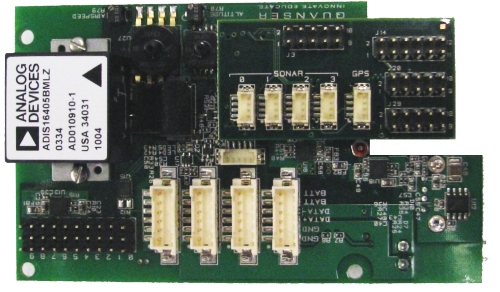
The Quanser's HiQ Aero is a board built and sold by Quanser Inc. The HiQ Aero (or simply HiQ) is based around Microchip's PIC microcontroller. The HiQ can only be used with QUARC when connected to a Gumstix Verdex embedded computer board. In this configuration, communication between the HiQ and the Verdex (which is where QUARC actually runs) is done using the Serial Peripheral Interface (SPI) bus. More precisely, the gumstix configured as the SPI master sends commands for performing I/O to the HiQ Aero which is set as the SPI slave. The following characteristics are of particular interest when using the HiQ Aero with QUARC:
The QUARC driver name for this card is hiq_aero.
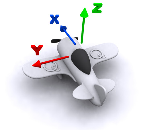
The HiQ Aero uses the Quanser standard reference frame for UAVs, as shown below:
To select the HiQ Aero HIL board, select the QUARC hiq_aero board type from the drop-down list on the Main tab of the HIL Initialize block. Please note that only one HiQ Aero card can be connected to a Verdex board and is supported in the system. The QUARC controller runs on the Verdex board and communicates with the HiQ Aero firmware using SPI.
| Note that the Linux Verdex target must be selected to use the HiQ Aero board, as it is connected to the Verdex board. |
The HiQ daughterboard provides I/O available through the HIL blockset with the 'hiq_aero' board type as well as the 'verdex' board type. The Gumstix reconfigurable digital I/O lines (e.g., GUM GPIO 63) are accessed via the HIL blockset using the Gumstix board type 'verdex' (see the Gumstix Verdex help page for details).
GPS data is accessible through the GPS NMEA block.
The Gumstix serial ports provided on the HiQ daughterboard are the IR UART, BT UART, and the FF UART (labeled GUM IR RXD/TXD, GUM BT RXD/TXD, and GUM FF RXD/TXD). The FF, BT, and IR UARTS are assigned serial ports 0, 1, and 2, respectively. The BT UART is used for the GPS header (J27) but can also be used for other purposes. Note that the FF UART serves as the default Linux console on the Gumstix and using this UART during boot might interrupt the Gumstix boot sequence. The Gumstix serial ports can be utilized through the QUARC Communications blockset and the Quanser Stream API (see QUARC Communications Protocols).
The HiQ I/O channels are described below. The PIC GPIO channels and Gumstix I2C are not currently supported.
Clocks
There are currently no configuration options for the HiQ Aero clocks.
Analog Inputs
The HiQ Aero driver supports 6 analog inputs. Hence, analog input channel numbers range from 0 to 5.
Analog Outputs
The HiQ Aero card does not support analog outputs.
Digital Inputs
The HiQ Aero card does not support digital inputs.
Digital Outputs
The HiQ Aero card does not support digital outputs.
Encoder Inputs
The HiQ Aero card does not support encoder inputs.
PWM Outputs
The HiQ Aero driver supports ten (10) PWM output channels, using two of the HiQ Aero hardware clocks. Hence, PWM output channels range from 0 to 9.
In order to configure the PWM mode or frequency, or to set the value of the PWM outputs when the model is loaded or unloaded, the PWM
outputs must be configured on the HIL Initialize block's
PWM Outputs tab. Set the PWM output channels field to all the PWM output channels that will be used on the
board for the current diagram. For example, enter 0:1 to indicate channels 0 and 1. Specify 1 to indicate channel 1 alone.
The PWM output frequency (a.k.a., pulse rate) is suitable to drive R/C servos. Specifically, it is set to 50 Hz, which is equivalent to a PWM
output period of 20 ms. Hence, set the PWM output mode field to 0 the duty cycle output mode. The HiQ Aero driver does not
currently support the frequency and period PWM output modes. Then set the
"Frequencies in Hz or duty cycle" field to 50 Hz, the desired frequency. The HiQ Aero driver
supports duty cycles ranging from 2.5% (i.e., a 0.5-ms pulse width) to 12.5% (i.e., a 2.5-ms pulse width), which is suitable for typical R/C
servo applications. Finally, set the Initial PWM outputs and Final PWM outputs fields to the desired
initial and final duty cycles, respectively. For example, enter 0.075 to indicate a 7.5 % duty cycle. A 7.5% duty cycle (i.e., a 1.5-ms
pulse width) typically corresponds to the neutral position for R/C servos. If the vectors specified in these fields are shorter than the
channel vector, the value of the last element in the vector will be used for the rest of the channels. Hence, a scalar value will apply to all
channels specified in the PWM output channels field.
Other Inputs
The specific Other Inputs channels of the HiQ Aero board are described in the table below. SI units are used.
|
Other Input Channel |
Measurement Description |
Units |
|---|---|---|
|
3, 4, 5, 6 |
Sonar distance measurement |
(m) |
|
3000, 3001, 3002 |
Angular velocity around the x-, y-, and z-axis, respectively (from gyroscope) |
(rad/s) |
|
4000, 4001, 4002 |
Linear acceleration along the x-, y-, and z-axis, respectively (from accelerometer) |
(m/s2) |
|
8000, 8001, 8002 |
Magnetic field along the x-, y-, and z-axis, respectively (from magnetometer) |
(G) |
|
9000, 9001 |
Pressure measurements from airspeed and altitude pressure sensors, respectively. |
(Pa) |
|
11000 |
Battery operating capacity (0.0 to 1.0) |
(%) |
|
20000 - 20007 |
Receiver input channels |
(s) |
Channel numbers for Other Input or Output channels use predefined ranges for each type of measurement to ensure consistency between data acquisition devices. Refer to QUARC Other Channels for a list of the Other Input or Output channel number ranges defined for any HIL Data Acquisition Card and their SI units.
Other Outputs
The HiQ Aero card does not support other outputs.
Interrupts
The HiQ Aero card, or its driver, does not support any interrupt sources.
Watchdog
The HiQ Aero card does not support a watchdog timer.
Board-Specific Options
The HiQ Aero card does not support any board-specific options.
Properties
The HiQ Aero card does not support any properties.
Connectors
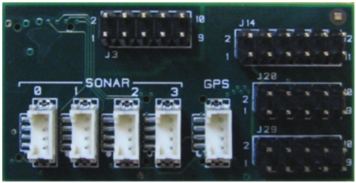
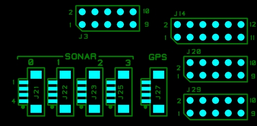
The HiQ daughterboard provides various inputs and outputs for general purpose use as well as the sonar inputs. The HiQ daughterboard is shown below with its pin layout and the following tables contain the header definitions.
J3 Header
| 10 | ← Analog input 1 |
| 9 | ← Analog input 0 |
| 8 | ← Analog input 3 |
| 7 | ← Analog input 2 |
| 6 | ← Analog input 5 |
| 5 | ← Analog input 4 |
| 4 | ― +3.3V |
| 3 | ― Analog GND |
| 2 | ― +5V |
| 1 | ― Analog GND |
J14 Header
| 12 | ↔ GUM GPIO 64 |
| 11 | ↔ PIC GPIO 1 |
| 10 | ↔ GUM GPIO 59 |
| 9 | ↔ GUM GPIO 62 |
| 8 | ↔ GUM GPIO 65 |
| 7 | ↔ GUM GPIO 63 |
| 6 | ↔ GUM I2C SCL |
| 5 | ↔ GUM I2C SDA |
| 4 | ↔ PIC GPIO 0 |
| 3 | ― GND |
| 2 | ― +3.3V |
| 1 | ― GND |
J20 Header
| 10 | ← GUM BT CTS |
| 9 | → GUM FF TXD |
| 8 | → GUM BT RTS |
| 7 | → GUM FF RTS |
| 6 | ← GUM FF CTS |
| 5 | ← GUM IR RXD |
| 4 | → GUM IR TXD |
| 3 | ← GUM FF RXD |
| 2 | ― +3.3V |
| 1 | ― GND |
J29 Header
| 10 | ↔ GUM GPIO 77 |
| 9 | ↔ GUM GPIO 66 |
| 8 | ↔ GUM GPIO 61 |
| 7 | ↔ GUM GPIO 60 |
| 6 | ― +5.5V |
| 5 | ↔ GUM GPIO 58 |
| 4 | ― +4V |
| 3 | ― GND |
| 2 | ― +3.3V |
| 1 | ― GND |
Sonar (J21, J22, J23, J25)
| 4 | ― +3.3V |
| 3 | → Trigger |
| 2 | ← Input compare |
| 1 | ― GND |
GPS (J27)
| 4 | ― +4V |
| 3 | ← GUM BT RXD |
| 2 | → GUM BT TXD |
| 1 | ― GND |
Legend
→▯← | = | input |
←▯→ | = | output |
↔▯↔ | = | bidirectional I/O |
= | unspecified voltage | |
= | power | |
= | ground |
Targets
|
Target |
Supported |
Comments |
|---|---|---|
|
No |
Not supported. |
|
|
No |
Not supported. |
|
|
No |
Not supported. |
|
|
No |
Not supported. |
|
|
No |
Not supported. |
|
|
No |
Not supported. |
|
|
No |
Not supported. |
|
|
No |
Not supported. |
|
|
No |
Not supported. |
|
|
No |
Not supported. |
|
|
No |
Not supported. |
|
|
No |
Not supported. |
|
|
No |
Not supported. |
|
|
Yes |
Fully supported. |
|
|
No |
Not supported. |
|
|
Rapid Simulation (RSIM) Target |
Yes |
Supported with no communication to the hardware. |
|
Normal simulation |
Yes |
Supported with no communication to the hardware. |
See Also
Copyright ©2026 Quanser Inc. This page was generated 2026-05-13. Submit feedback to Quanser about this page.
Link to this page.

