
KUKA LBR FRI Timebase
Reads and writes to a 7-DOF KUKA LBR manipulator (e.g., LBR iiwa, LBR Med) at the sampling rate specified by the robot cabinet application (e.g., 1 ms) and acts as a timebase for the model.
Library
QUARC Targets/Devices/Third-Party/KUKA/Robots/Interfacing MATLAB Command Line Click to copy the following command line to the clipboard. Then paste it in the MATLAB Command Window: qc_open_library('quarc_library/Devices/Third-Party/KUKA/Robots/Interfacing')
Description
The KUKA LBR FRI Timebase block reads and writes to a 7-DOF KUKA lightweight cobot, e.g., KUKA LBR iiwa, at the sampling rate specified by the robot cabinet application, e.g., typically 1 kHz, and acts as a timebase for the model. The KUKA LBR FRI Timebase block outputs the robot position, torque and state information. In terms of its inputs, the KUKA LBR FRI Timebase block provides support for the joint position, joint torque and wrench command modes, as well as, with FRI 2.5, the Cartesian pose (quaternion) and Cartesian pose (matrix) command modes.
To interface to the KUKA lightweight cobots, the KUKA LBR FRI Timebase block requires the KUKA Sunrise.FRI (Fast Robot Interface) software toolbox and makes use of the FRI Client C++ Software Development Kit (SDK) provided by KUKA (under this license agreement). The KUKA FRI 1.16 and FRI 2.5 versions are supported.
The KUKA LBR FRI Timebase block reads and writes to the KUKA LBR manipulator at every sampling instant. The timebase for the model is provided by the block itself. Only one Timebase block may appear in the model. Multiple timebases for a model are not supported.
Limitations
CAUTION: Open Architecture Robot!
 This block is intended for experienced and expert users only!
When using this block, together with corresponding cabinet applications,
the KUKA robot becomes an open architecture system.
This block is intended for experienced and expert users only!
When using this block, together with corresponding cabinet applications,
the KUKA robot becomes an open architecture system.
Fully read this document and all relevant KUKA documentation, specifically the "KUKA_SunriseFRI_116_en.pdf" or "KUKA_SunriseFRI_25_en.pdf" manual, before operating the KUKA LBR manipulator. All software using this block supplied by Quanser is only to be considered a sample and should not be used on a regular basis. The user should develop and validate their own open architecture control software.
The user is solely responsible for the implementation and utilization of their open architecture controller application! Quanser and KUKA Robotics are not responsible for any material or bodily damage that may ensue from the use of this system.
Do not approach the robot when the arm or the controller are powered up! Install the robot in a safe location and ensure no personnel approaches the robot while it is in operation or while the arm is powered.
Installation Requirements
Sunrise Controller Configuration
 The KUKA Sunrise.FRI (Fast Robot Interface) version 1.16 or 2.5 should be installed
on the Sunrise cabinet.
On the Sunrise controller, the IP address for the KONI ethernet port
(a.k.a., KUKA Option Network Interface) must be set to 192.170.10.2,
with a subnet mask of 255.255.255.0 and a default gateway of 192.170.10.1.
The KUKA Sunrise.FRI (Fast Robot Interface) version 1.16 or 2.5 should be installed
on the Sunrise cabinet.
On the Sunrise controller, the IP address for the KONI ethernet port
(a.k.a., KUKA Option Network Interface) must be set to 192.170.10.2,
with a subnet mask of 255.255.255.0 and a default gateway of 192.170.10.1.
QUARC Target Configuration
For best deterministic behaviour, it is recommended to setup on the QUARC target machine
a dedicated (i.e., ad-hoc) network connection to the Sunrise cabinet KONI port.
The network adapter used on the QUARC target machine has to support full duplex mode
and should be configured with a static IP address set to, for example, 192.170.10.200,
with a subnet mask of 255.255.255.0 and a default gateway of 192.170.10.1.
The cabinet application communicates with the QUARC external machine (i.e., the QUARC target machine which is running the QUARC model) via a real-time-capable point-to-point network link. The exchanged data are transmitted via the ethernet UDP protocol. The robot cabinet application runs a Java application that connects using Sunrise.FRI (and acting as a UDP client) to the QUARC model containing this block (and acting as a UDP server). The FRI cabinet application (on the Sunrise controller) has to initiate the cyclical data exchange with the QUARC target machine at the pre-determined FRI update cycle.
Input Ports
jnt pos cmd
A 7-element vector of double values containing the joint angular position commands, in rad, to send to the 7-DOF robot.
jnt torque cmd
A 7-element vector of double values containing the joint torque commands, in N.m, to send to the 7-DOF robot.
This input port only exists when the Control Mode parameter is set to Joint Impedance.
wrench cmd
A 7-element vector of double values containing the Cartesian wrench commands, in N and N.m, to send to the 7-DOF robot.
This input port only exists when the Control Mode parameter is set to Cartesian Wrench.
Cart pose cmd
A 7-element vector of double values containing the Cartesian pose commands, to send to the 7-DOF robot, as a quaternion transformation vector (translations in mm). The pose describes the configured Tool Center Point (TCP) relative to the configured base frame. The interpolated redundancy value is used, which is the E1 redundancy strategy in FRI 2.5.
This input port only exists when the Control Mode parameter is set to Cartesian Pose (quaternion).
Cart pose (mat)
A 4x4 homogeneous transformation matrix of double values containing the Cartesian pose commands, to send to the 7-DOF robot. The first three columns and three rows represent the rotational matrix and the fourth column the 3-dimensional translation vector for directions X, Y, and Z (in mm). The pose describes the configured Tool Center Point (TCP) relative to the configured base frame. The interpolated redundancy value is used, which is the E1 redundancy strategy, in FRI 2.5.
This input port only exists when the Control Mode parameter is set to Cartesian Pose (matrix).
Output Ports
jnt angles
A 7-element vector of double values containing the robot measured joint angles, in radians (rad).
jnt IPO angles
A 7-element vector of double values containing the robot IPO joint angles, as determined by the cabinet interpolator, in radians (rad).
jnt torques
A 7-element vector of double values containing the robot measured joint torques, in N.m.
jnt cmd torques
A 7-element vector of double values containing the robot commanded joint torques, in N.m.
jnt ext torques
A 7-element vector of double values containing the robot joint external torques, in N.m.
Cart pose
A 7-element vector of double values containing the robot Cartesian pose, as a quaternion transformation vector (translations in mm). The pose describes the robot Tool Center Point (TCP) relative to the base frame.
Cart IPO pose
A 7-element vector of double values containing the robot interpolated Cartesian pose, as a quaternion transformation vector (translations in mm). The pose describes the robot TCP relative to the base frame.
Cart pose (mat)
A 4x4 homogeneous transformation matrix of double values containing the robot Cartesian pose. The first three columns and three rows represent the rotational matrix and the fourth column the 3-dimensional translation vector for directions X, Y, and Z (in mm). The pose describes the robot TCP relative to the base frame.
Cart IPO pose (mat)
A 4x4 homogeneous transformation matrix of double values containing the robot interpolated Cartesian pose. The first three columns and three rows represent the rotational matrix and the fourth column the 3-dimensional translation vector for directions X, Y, and Z (in mm). The pose describes the robot TCP relative to the base frame.
robot states
A 9-element vector of uint8 values indicating the values of the various different robot states. The table below specifies these robot states, together with their one-based position in the vector.
|
Index |
Description |
|---|---|
|
1 |
Control Mode |
|
2 |
Session State |
|
3 |
Safety State |
|
4 |
Connection Quality |
|
5 |
Operation Mode |
|
6 |
Drive State |
|
7 |
Client Command Mode |
|
8 |
Overlay Type |
|
9 |
Redundancy Strategy |
The following tables, below, give a description of these different robot states and their possible values.
The Control Mode value indicates the control mode of the robot drives.
The table below gives a description of its possible values.
|
Value |
Name |
Description |
|---|---|---|
|
0 |
POSITION_CONTROL_MODE |
Position control mode |
|
1 |
CART_IMP_CONTROL_MODE |
Cartesian impedance control mode |
|
2 |
JOINT_IMP_CONTROL_MODE |
Joint impedance control mode |
|
3 |
NO_CONTROL |
Drives are not used |
The Session State value indicates the state of the robot FRI session.
The table below gives a description of its possible values.
|
Value |
Name |
Description |
|---|---|---|
|
0 |
IDLE |
No FRI session available |
|
1 |
MONITORING_WAIT |
Monitoring mode with insufficient connection quality |
|
2 |
MONITORING_READY |
Monitoring mode with connection quality sufficient for command mode |
|
3 |
COMMANDING_WAIT |
Command mode about to start (overlay motion queued) |
|
4 |
COMMANDING_ACTIVE |
Command mode active |
The Safety State value indicates the robot controller's safety state.
The table below gives a description of its possible values.
|
Value |
Name |
Description |
|---|---|---|
|
0 |
NORMAL_OPERATION |
No safety stop request present |
|
1 |
SAFETY_STOP_LEVEL_0 |
Safety stop request STOP0 or STOP1 present |
|
2 |
SAFETY_STOP_LEVEL_1 |
Safety stop request STOP1 (on-path) present |
|
3 |
SAFETY_STOP_LEVEL_2 |
Safety stop request STOP2 present |
The Connection Quality value indicates the FRI connection quality.
The table below gives a description of its possible values.
|
Value |
Name |
Description |
|---|---|---|
|
0 |
POOR |
Poor connection quality |
|
1 |
FAIR |
Connection quality insufficient for command mode |
|
2 |
GOOD |
Connection quality sufficient for command mode |
|
3 |
EXCELLENT |
Excellent connection quality |
The Operation Mode value indicates the robot controller's current mode of operation.
The table below gives a description of its possible values.
|
Value |
Name |
Description |
|---|---|---|
|
0 |
TEST_MODE_1 |
Test mode 1 with reduced speed (T1) |
|
1 |
TEST_MODE_2 |
Test mode 2 (T2) |
|
2 |
AUTOMATIC_MODE |
Automatic operation mode (AUT) |
The Drive State value indicates the robot drive state.
The table below gives a description of its possible values.
|
Value |
Name |
Description |
|---|---|---|
|
0 |
OFF |
Drive is not being used |
|
1 |
TRANSITIONING |
Drive is in a transitioning state (before or after motion) |
|
2 |
ACTIVE |
Drive is being actively commanded |
The Client Command Mode value indicates the client (i.e., QUARC model) command mode
of the robot FRI session.
The table below gives a description of its possible values.
|
Value |
Name |
Description |
|---|---|---|
|
0 |
NO_COMMAND_MODE |
No client command mode available |
|
1 |
JOINT_POSITION |
Commanding joint positions by the client |
|
2 |
WRENCH |
Commanding wrenches and joint positions by the client |
|
3 |
TORQUE |
Commanding joint torques and joint positions by the client |
|
4 |
CARTESIAN_POSE |
Commanding Cartesian poses by the client (FRI 2.5) |
The Overlay Type value indicates the motion overlay type.
The table below gives a description of its possible values.
|
Value |
Name |
Description |
|---|---|---|
|
0 |
NO_OVERLAY |
No overlay type available |
|
1 |
JOINT |
Joint overlay |
|
2 |
CARTESIAN |
Cartesian overlay |
The Redundancy Strategy value indicates the redundancy strategy type.
This is available with FRI 2.5.
The table below gives a description of its possible values.
|
Value |
Name |
Description |
|---|---|---|
|
0 |
E1 |
E1 redundancy strategy |
|
1 |
NO_STRATEGY |
No redundancy strategy |
status
A 5-element vector of double values indicating the robot status values. The table below details these status values, together with their one-based position in the vector.
|
Index |
Name |
Description |
|---|---|---|
|
1 |
Desired sample time |
Desired FRI communication period and model sample time (s) |
|
2 |
Timestamp |
Robot timestamp in Unix time (us) |
|
3 |
Tracking Performance |
Robot tracking performance [0-1] |
|
4 |
Measured redundancy value |
Currently measured redundancy value, in radians. Available with FRI 2.5. |
|
5 |
IPO redundancy value |
Current redundancy value of the interpolator, in radians. Available with FRI 2.5. |
Desired sample time indicates, in seconds (s),
the desired FRI communication period, as set by the cabinet application,
as well as the QUARC model sample time.
Timestamp indicates, in microseconds (us),
the robot application current timestamp value in epoch Unix time,
as determined by the Sunrise cabinet.
As long as the timestamp value changes and is being updated, the FRI cabinet application is running and connected.
Tracking Performance indicates the robot tracking performance,
as determined by the Sunrise cabinet.
It is a value between 0.0 and 1.0, where 1.0 corresponds to optimal tracking.
Parameters and Dialog Box
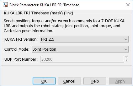
KUKA FRI version
Using this drop-down menu, select the FRI (Fast Robot Interface) version that is installed
onto the LBR Sunrise cabinet, e.g., FRI 1.16 or FRI 2.5.
Control Mode
The control mode in which to operate the LBR is determined by this field.
The table below specifies the possible selection choices (from the drop-down menu),
together with the corresponding cabinet Java application for each.
These Sunrise cabinet applications use the KUKA RoboticsAPI Java programming interface,
and require the cabinet to be set to the Automatic operation mode (i.e., AUT).
The control mode defined by the menu selection and the selected cabinet application must be consistent and match.
|
Selection |
Cabinet Application |
Description |
|---|---|---|
|
Joint Position |
QJntPosDriver |
Joint position control mode |
|
Joint Impedance |
QJntTrqDriver |
Joint impedance control mode |
|
Cartesian Wrench |
QWrenchDriver |
Cartesian wrench control mode |
|
Cartesian Pose (quaternion) |
QCartPoseDriver |
Cartesian pose control mode (FRI 2.5) |
|
Cartesian Pose (matrix) |
QCartPoseDriver |
Cartesian pose control mode (FRI 2.5) |
UDP Port Number
The UDP port number used to communicate between the QUARC model (running on the external target machine) and the LBR Sunrise cabinet. By default, the UDP port used is set to port 30200.
Targets
|
Target Name |
Compatible* |
Model Referencing |
Comments |
|---|---|---|---|
|
Yes |
Yes |
||
|
Yes |
Yes |
||
|
No |
No |
||
|
No |
No |
||
|
No |
No |
||
|
No |
No |
||
|
No |
No |
||
|
No |
No |
||
|
No |
No |
||
|
No |
No |
||
|
No |
No |
||
|
No |
No |
||
|
No |
No |
||
|
No |
No |
Last fully supported in QUARC 2018. |
|
|
Rapid Simulation (RSIM) Target |
No |
No |
|
|
S-Function Target |
No |
N/A |
Old technology. Use model referencing instead. |
|
Normal simulation |
No |
No |
See Also
Copyright ©2026 Quanser Inc. This page was generated 2026-05-13. Submit feedback to Quanser about this page.
Link to this page.