
Robots
Advanced robotic control applications require sophisticated mathematical algorithms, such as forward and inverse kinematics. QUARC provides many of these essential algorithms in its blocksets for industrial open-architecture robots. QUARC presently supplies blocksets for the CRS Catalyst-5 and A465 robots from Thermo Fisher Scientific and the PA10 robot from Mitsubishi. The Schunk gripper is also supported by QUARC. This gripper is a rugged industrial robotic end-effector. This section provides a general overview of each robot and the gripper in addition to descriptions of the blocks provided for each one and information on how to use these blocks.
There are a number of terms used in the block names provided for the robots such as joint angles, world coordinates, stance and kinematics. The definition of each term is provided below:
Joint Angles
The angles of all the joints of the robot in radians. Joint space refers to the robot position using the joint angles as coordinates.
World coordinates
The position of the robot's end-effector in Cartesian coordinates or task space. The world coordinates
consist of the X, Y and Z coordinates in metres and the roll, yaw and pitch orientations in radians.
Kinematics
The geometric relationship between joint space coordinates and world coordinates. In particular, the forward kinematics map joint angles of the robot to the world coordinates of the end-effector. Similarly, the inverse kinematics map the world coordinates of the end-effector back to the joint angles of the robot.
Stance
The stance refers to a particular orientation or gesture of the robot. For example, the stance could be reaching forward, reaching backward or the wrist being flipped. The stance is required when the same end-effector coordinates can be achieved by more than one orientation of the robot joints.
Please use the following list to refer to the corresponding section for each robot and the gripper:
CRS Catalyst-5
The CRS Catalyst-5 is a 5 degree-of-freedom articulated robot mounted on a linear track. It has 5 joints powered by 5 motors and one linear track powered by one actuator. Figure below depicts the CRS Catalyst-5 robot.
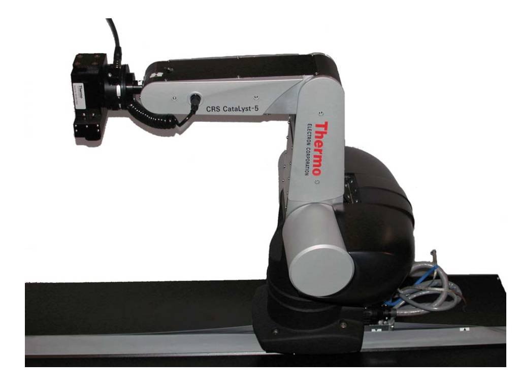
The system is supplied with the C500C controller and the RAPL3 programming language to teach the robot to perform specific tasks. The C500C controller contains a PID controller for each actuator its structure cannot be modified. It is a closed-architecture controller. However, Quanser has designed an interface to the C500C controller that allows currents to be sent directly to the motors. This open architecture (OA) interface gives maximum flexibility to the roboticist, who can now implement their own feedback control system. The user can switch between this open architecture interface and the closed-architecture C500C controller seamlessly. For more information about this robot, please refer to its reference manual included in the package.
The blocks provided for the CRS Catalyst-5 robot can be found in the QUARC Targets/Devices /CRS/Robots/CAT5 library in the Simulink Library Browser. For each block's reference page, right click on the block in the Library Browser window or in a Simulink diagam and select the menu item, or click on the button in the block's parameters dialog.
The Forward Kinematics and Joint Angles to World Coordinates blocks are basically the same. They both perform the forward kinematics described earlier. Likewise, the Inverse Kinematics and World Coordinates to Joint Angles blocks are functionally identical. They both perform the inverse kinematics described earlier. The Joint Torques to Motor Inputs block converts the joint torques to motor inputs (voltages or currents) and the Motor Pulses to Joint Angles block is used to translate the counts read from the joint encoders into joint angles.
These blocks may be combined in order to control the motion of the CRS Catalyst-5 robot. Below is a Simulink diagram of a sample robot control system using the blocks mentioned above.
The desired position for the end-effector is commanded in world coordinates. It gets converted to joint angles using the Inverse Kinematics block. Note that the second output of the block is for error checking. For more information, please refer to the Inverse Kinematics block's help page.
The Position Control block is just a template for the main controller and is not an actual block in the Simulink Library. The user has to create their own controller subsystem in place of this block. In this example, position control is used which means that the joint positions are controlled. Another type of control algorithm would be velocity control where you control the joint velocities. The Plant block represents the robot itself, to which the joint torques are output and from which the joints' encoder counts are read. The encoder counts read from the robot joints are converted to joint angles in order to be used in the feedback loop of the control system as shown in the figure.
The converted joint angles are again converted to world coordinates in this example for monitoring purposes. Using world coordinates, or task space, rather than joint angles is more convenient because tasks are typically represented in the Cartesion world coordinates of the end-effector rather than joint angles. It is even possible to do the control in task space. With QUARC and Quanser's open-architecture solutions for industrial robots, you have the flexibility and the power to implement the control system you need!
 This example explains the basic concepts of CRS Catalyst-5 robot control using the provided blocks. It should not be used as a template
for actual control design. There are restrictions, limitations and safety issues that need to be taken into account to operate and control
the robot safely. Please refer to the control manual provided with the robot package for detailed information on the robot control design.
This example explains the basic concepts of CRS Catalyst-5 robot control using the provided blocks. It should not be used as a template
for actual control design. There are restrictions, limitations and safety issues that need to be taken into account to operate and control
the robot safely. Please refer to the control manual provided with the robot package for detailed information on the robot control design.
Mitsubishi PA10
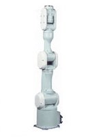
The Mitsubishi PA10 is a 6 degree-of-freedom articulated robot mounted on an arm stand as shown in the figure below. It has 6 joints powered by 6 motors and 6 encoders to measure the coordinates of the joints. The motors are harmonic drives, which yield smooth and accurate robot motion.
The system is supplied with a controller unit which consists of servo amplifiers to drive the 6 motors and a power supply. The PA10 robot is an open architecture system. The PC communicates with the PA10 controller via ARCNET, a networking technology that is popular in robotic applications. This means advanced experiments in robotics such as coupled control, adaptive control and other advanced algorithms can be implemented. The user is solely responsible for implementing a stable feedback control system.
There is only one block provided by QUARC for this robot called the PA10 Control block which can be found under the QUARC Targets/Devices/Mitsubishi/Robots/PA10/Interfacing library in the Simulink Library browser. This block provides the necessary interface to the PA10 robot. For information on this block, you can right click on the block in the Library Browser or in a Simulink diagam and select the menu item, or click on the button in the block's parameters dialog.
There are two control modes that can be chosen for the PA10 Control block: torque mode, in which the torques of the joint motors are commanded, and velocity mode, in which the joint velocities are commanded. Depending on the mode chosen, you either have joint torques or joint velocities as inputs to the block. The forward/inverse kinematics of the robot are not included in the blockset. The user is responsible for deriving the robot kinematics. You can refer to the Mitsubishi PA10 reference manual for the kinematics.
Once the kinematics are derived, you can create a model that takes a reference position in world coordinates and converts that position internally into joint angles. Using the commanded and measured joint angles, the joint torques (when torque mode is used) needed to drive the motors may then be computed. Alternatively, the reference position in joint space may be differentiated to get joint velocities (when velocity mode is used) and fed into the PA10 Control block. For a detailed discussion on how to design an open-architecture controller for the Mitsubishi PA10 robot, refer to the robot's control manual.
Schunk Gripper
The Schunk gripper is an end-effector that can be mounted on the robot and be used to grip tools. The Schunk gripper is illustrated below.
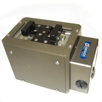
For the gripper specifications and general information on how to set up the system, please refer to the reference manual provided with the package.
QUARC provides the Schunk Gripper Control block to interface with this gripper. This block can be found under the QUARC Targets/Devices/Schunk/Grippers library in the Simulink Library browser. For information on this block, you can right click on the block in the Library Browser or in a Simulink diagam and select the menu item, or click on the button in the block's parameters dialog.
The Schunk gripper can be controlled in position, velocity or current control mode. The Schunk Gripper Control block communicates with the gripper over a serial RS232 connection. It sends position, velocity or current commands to the gripper module over an RS232 connection and receives the module's position, velocity and current. The block supports three modes: position control mode, velocity control mode, and current control mode. This mode may be specified internally in the block parameters, or externally via an extra input to the block. Using an external block input allows the mode of operation to change during block execution. If the control mode is specified via the block's Control mode parameter then the control mode is fixed for the duration of the model's execution. For more information, please refer to the Schunk Gripper Control block's help page.
The Schunk Gripper Control block supplies the only interface required to implement a stable feedback control system using the Schunk Gripper. Its outputs may also be used for monitoring purposes. The user is responsible for implementing a control system that meets the requirements of the Schunk Gripper and prevents damage to the device.
Copyright ©2026 Quanser Inc. This page was generated 2026-05-13. Submit feedback to Quanser about this page.
Link to this page.