

KUKA RSI
Depending on the control mode, sends Cartesian position correction, or Cartesian velocity, or joint position correction, or joint velocity commands to a 6-DOF KUKA robot and outputs the robot actual Cartesian positions, joint angles and gear torques for each joint.
Library
QUARC Targets/Devices/Third-Party/KUKA/Robots/Interfacing MATLAB Command Line Click to copy the following command line to the clipboard. Then paste it in the MATLAB Command Window: qc_open_library('quarc_library/Devices/Third-Party/KUKA/Robots/Interfacing')
Description
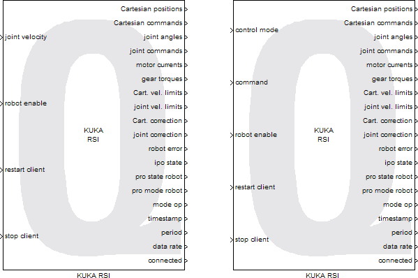
The KUKA RSI block uses the KUKA.RobotSensorInterface (RSI) networking technology to interface to KUKA 6-DOF articulated robots with the following KUKA Robot Controllers (KRC): KR C5, KR C4, KR C2, and KR C2sr. Both Normal RSI and Fast RSI modes are supported.
Depending on the user-selected control mode, the KUKA RSI block sends Cartesian position correction, or Cartesian velocity, or joint position correction, or joint velocity commands to the 6-DOF KUKA robot and outputs the robot actual Cartesian positions, joint angles and gear torques for each joint.
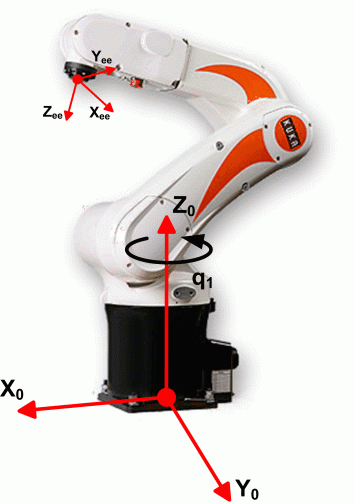
The Cartesian reference frame used is shown below.
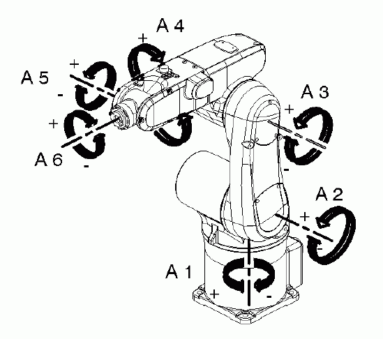
When operating the robot in joint mode, the direction of motion of each axis is represented by the following schematic (taken from the KUKA "KR 5 sixx R650, R850 Specification" manual).
Limitations
CAUTION: Open Architecture Robot!
 When using this block, the KUKA robot becomes an open architecture system.
This block is intended for mature and experienced engineers only!
The user must understand the difference between an industrial controller and an open architecture controller.
If it is unclear contact Quanser immediately at tech@quanser.com.
The user is solely responsible for the implementation of the open architecture controller! Quanser and KUKA Robotics are not responsible for any material or bodily damage that ensues from the use of this equipment.
Do not approach the robot when the arm or the controller are powered up! Install the robot in a safe location and ensure no personnel approaches the robot while it is in operation or while the arm is powered.
All software using this block supplied by Quanser is only to be considered a sample and should not be used on a regular basis. The user should write their own open architecture control software.
Fully read this document before connecting the QUARC external PC to the KUKA robot controller.
Operating Procedure
 The robot controller communicates with the QUARC external machine (i.e., the QUARC target machine which is running the QUARC model)
via a real-time-capable point-to-point network link.
The exchanged data are transmitted via the ethernet TCP/IP protocol.
The robot controller runs Quanser's KRL (Kuka Robot Language) application that connects as a TCP/IP client
to the QUARC model containing this block.
The QUARC model containing this block sets up a TCP/IP communication server and must be started first (i.e. before Quanser's KRL application),
so that the KRL client controller can connect.
Quanser's KRL application (on the controller) has to initiate the cyclical data exchange with the QUARC target machine
at the RSI update cycle of 12 milliseconds (ms) with Normal RSI, or 4 ms with Fast RSI.
With the KR C2sr, if a RS-232 serial connection has been established between the QUARC machine and the robot controller, and the operating guidelines listed below can be followed.
With the KR C5, KR C4, and KR C2, where no RS-232 serial connection exists between the QUARC machine and the robot controller, the operating guidelines listed below should be followed.
Maintenance Procedure
 The robot arm and robot controller maintenance procedures and schedules, as described in the appropriate KUKA manuals, must be respected and followed.
Installation Requirements
KR C5 Controller Configuration
 The KUKA.RobotSensorInterface (RSI) version 5.0 (or later) should be installed
on the KR C5 robot controller.
Typically, the IP address of the robot controller should be set to 172.31.1.147.
KR C4 Controller Configuration
 The KUKA.RobotSensorInterface (RSI) version 4.1 (or later) should be installed
on the KR C4 robot controller.
Typically, the IP address of the robot controller should be set to 192.168.1.2.
KR C2sr or KR C2 Controller Configuration
 When the KUKA robot is paired with a KR C2sr or KR C2 controller,
a VxWin network card must be first installed in the robot controller,
in order to ensure deterministic communication with the QUARC external PC.
The 3COM 3C905CX-TX-M 10/100 PCI network interface card is recommended.
Then the KUKA.RobotSensorInterface (RSI) version 2.2 or 2.3 must also be installed
with RealTime (RT) ethernet support on the robot controller.
Typically the IP address of the robot controller must be set to 192.168.1.2.
QUARC Target Configuration
 For best deterministic behaviour, it is recommended to setup on the QUARC target machine
a dedicated (i.e., ad-hoc) network connection to the KR C2sr or KR C2 controller.
The network adapter used on the QUARC target machine should be 10Mbit/s or 100Mbit/s compatible in full duplex mode.
It has to be configured with a static IP address set to 192.168.1.10, with a subnet mask of 255.255.0.0
and a default gateway of 192.168.1.1.
Service Jumper Plug X11
 To prevent personal injury and material damage, the KUKA Control Panel (KCP) must be connected to the KR C2sr or KR C2 controller
and its emergency stop (E-stop) button must be within reach when operating the robot.
As a consequence, another external E-stop might not be connected to the system, in which case
a service jumper plug X11 is required.
For the KR C2sr, the service jumper plug X11 is a 37-contact SUB-D female socket and
its wiring schematic is provided in the KUKA "KR C2sr Operating Instructions" manual.
For the KR C2, the service jumper plug X11 is a 108-pin Harting plug.
If KR C2sr: X12 Mini I/O Interface
 The physical I/Os provided by the KR C2sr controller need to be used.
The X12 mini I/O interface is a 37-contact SUB-D female socket.
The Quanser-provided X12 connector must be plugged in the KR C2sr controller.
If KR C2: DeviceNet Module
 If the KR C2 controller is used, DeviceNet modules are required to provide four (4) digital outputs
and four (4) digital inputs. For example the following DeviceNet module assembly could be used:
a WAGO 750-306 DeviceNet coupler module,
with a WAGO 750-504 four-channel digital output module,
and a WAGO 750-403 four-channel digital input module,
terminated by a WAGO 750-600 end terminal.
The KR C2 DeviceNet module assembly is typically configured with a MACID set to 1
and a baud rate set to 125 kbit/s.
If KR C2sr: Serial Connection
 The null modem RS-232 serial connection between the external machine (running QUARC)
and the KR C2sr or KR C2 controller is optional but highly recommended.
If used, the null modem cable must be connected to the COM2 or COM3 port (i.e., the real-time serial port)
of the KR C2sr or KR C2 controller, respectively.
The serial connection is required to start Quanser's KRL application remotely from the QUARC machine and seamlessly from QUARC.
It is also used by the robot controller to send an acknowledgement when Quanser's KRL application has terminated.
When stopping model, this in turn allows this block to cleanly and reliably shut down the RSI connection.
Input Ports
control mode
This port appears when the Control Mode Source is set to external(input port), and
provides, as a single uint8 value, the control mode in which to operate the robot.
The table below gives a description of the control mode values that are allowed.
|
Control Mode |
Description |
|---|---|
|
1 |
Cartesian position correction |
|
2 |
Cartesian velocity |
|
3 |
Joint position correction |
|
4 |
Joint velocity |
command/Cartesian correction/Cartesian velocity/joint correction/joint velocity
A 6-element vector of double values containing the command signals to the 6-DOF robot.
The port name "command" appears when the Control Mode Source is set to external(input port).
Otherwise when the Control Mode Source is set to internal(dialog parameter),
the port name reflects the control mode selected from the dialog drop-down menu.
Depending on the current control mode, this 6-element vector contains either
the Cartesian position correction commands (in m and rad),
the Cartesian velocity commands (in m/s and rad/s),
the joint position correction commands (in rad), or
the joint velocity commands (in rad/s) to the 6-DOF robot.
robot enable
A single boolean value used to remotely turn the robot drives either on (true) or off (false). This value must be true (i.e., drives on command) when starting the model containing this block and when the Quanser's KRL application starts/connects. Please allow a 2-second delay when turning the drives on or off.
restart client
A single boolean value used to, when true, restart the Quanser's KRL application remotely from the QUARC machine. This functionality assumes that a null modem RS-232 serial connection has been established between the external machine (running QUARC) and the KR C2sr controller and that the controller is in EXT (i.e., automatic external) mode.
stop client
A single boolean value used to, when true, remotely disconnect and shut down Quanser's KRL application running on the robot controller.
Output Ports
Cartesian positions
A 6-element vector of double values containing the robot Cartesian absolute positions in SI units. The X, Y, and Z linear positions are expressed in meters (m) while the A, B, and C angles are expressed in radians (rad).
Cartesian commands
A 6-element vector of double values containing the robot Cartesian absolute position commands in SI units. The X, Y, and Z linear position commands are expressed in meters (m) while the A, B, and C angular position commands are expressed in radians (rad).
joint angles
A 6-element vector of double values containing the robot axis absolute angles in radians (rad).
joint commands
A 6-element vector of double values containing the robot joint absolute angular position commands in radians (rad).
motor currents
A 6-element vector of double values containing the joint motor currents in Amperes (A).
gear torques
A 6-element vector of double values containing the joint motor gear torques in Newton meters (N.m).
Cart. vel. limits
A 12-element vector of boolean values containing the minimum and maximum Cartesian velocity limit flags for each Cartesian axis, as determined by the robot controller. The vector contains the minimum Cartesian velocity limit flag immediately followed by the maximum Cartesian velocity limit flag for each Cartesian axis. A Cartesian velocity limit is reached (i.e., saturation) when its corresponding flag is set (true).
joint vel. limits
A 12-element vector of boolean values containing the minimum and maximum velocity limit flags for each joint, as determined by the robot controller. The vector contains the minimum velocity limit flag immediately followed by the maximum velocity limit flag for each joint. A joint velocity limit is reached (i.e., saturation) when its corresponding flag is set (true).
Cart. correction
A uint8 value indicating the value of the controller correction active signal for the Cartesian path. The table below gives a description of the possible Cartesian correction values.
|
Value |
Description |
|---|---|
|
0 |
Interpolator not active |
|
1 |
Correction active |
|
2 |
Correction out of range |
joint correction
A uint8 value indicating the value of the controller correction active signal for all the joints. The table below gives a description of the possible joint correction values.
|
Value |
Description |
|---|---|
|
0 |
Interpolator not active |
|
1 |
Correction active |
|
2 |
Correction out of range |
robot error
A uint32 value reflecting the main error codes of the robot controller in its current state. Refer to the "KR C... System Messages KUKA System Software (KSS)" manual for a full description of the KUKA error codes.
ipo state
An 8-element vector of boolean values indicating the status of the robot interpolator (a.k.a., IPO). The table below gives a description of the ipo state bit values.
|
Bit |
Description |
|---|---|
|
Bit 1 |
Interpolator is working |
|
Bit 2 |
Start was restarted after stop |
|
Bit 3 |
Pathstop normal |
|
Bit 4 |
Pathstop fast |
|
Bit 5 |
Energy stop |
|
Bit 6 |
Energy stop, robot is still in motion |
|
Bit 7 |
Current movement is Cartesian |
|
Bit 8 |
Interpolator still smoothing |
pro state robot
A uint8 value indicating the state of the robot interpreter. The table below gives a description of the possible pro state robot values.
|
Value |
Description |
|---|---|
|
1 |
FREE |
|
2 |
RESET |
|
3 |
ACTIVE |
|
4 |
STOP |
|
5 |
ENDED |
pro mode robot
A uint8 value indicating the mode of the robot interpreter. The table below gives a description of the possible pro mode robot values.
|
Value |
Description |
|---|---|
|
1 |
I_STEP |
|
2 |
I_MSTEP |
|
3 |
P_STEP |
|
4 |
C_STEP |
|
5 |
B_STEP |
|
6 |
GO |
|
7 |
Invalid |
mode op
A uint8 value indicating the value of the robot operating mode, as set by the KUKA Control Panel (KCP) connected to the robot controller. The table below gives a description of the possible mode op values.
|
Value |
Description |
|---|---|
|
1 |
T1 (T1 mode) |
|
2 |
T2 (T2 mode) |
|
3 |
AUT (automatic mode) |
|
4 |
EXT (external mode) |
|
5 |
Invalid |
timestamp
A uint32 value representing the lower 32 bits of the 64-bit interpolation cycle counter (IPOC). The IPOC indicates the current timestamp of the communication data packet from the robot controller that generates it automatically. As long as the timestamp value changes and is updated, the Quanser's KRL application is running and connected.
period
A double value representing the communication loop time (including network communication delays) in seconds between when the block input data are sent to the device and when the device data are received. As long as the period value changes and is updated, the Quanser's KRL application is running and connected.
data rate
A double value representing the communication data rate to the 6-DOF robot system,
expressed in bytes per second (i.e., B/s or Bps).
This corresponds to the total number of bytes that are received and sent over one period.
connected
A boolean value indicating whether the Quanser's KRL application is connected (true) or not (false).
Data Type Support
The control mode input, if it appears, is of type uint8. The command/Cartesian correction/Cartesian velocity/joint correction/joint velocity input is of type double. All the other inputs are of type boolean.
The Cartesian positions, Cartesian commands, joint angles, joint commands, motor currents, and gear torques outputs are of type double. The Cartesian correction, joint correction, pro state robot, pro mode robot, and mode op outputs are of type uint8. The robot error and timestamp outputs are of type uint32. All the other outputs are of type boolean.
Parameters and Dialog Box
Individual Panes
Main Pane
The Main pane of the dialog appears as follows:
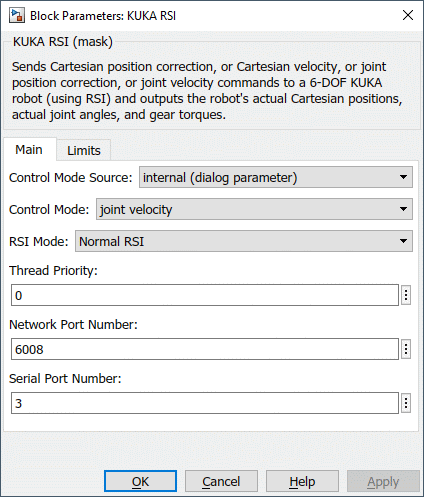
Control Mode Source
The source of the control mode in which to operate the robot is determined by this field
to be internal (dialog parameter) or external (block input).
Control Mode
This parameter is enabled when the Control Mode Source is set to
internal(dialog parameter). It provides the control mode in which to operate the robot.
The following control modes can be selected:
Cartesian position correction, Cartesian velocity, joint position correction, or joint velocity.
Note that each control mode utilizes the same input signal to the block,
so it is crucial that the user checks to make sure the robot is operated in the correct control mode.
RSI Mode
The following RSI modes can be selected: Normal RSI or Fast RSI.
When using the KR C5 or KR C4 robot controller, always select the Fast RSI mode.
When using the KR C2 or KR C2sr robot controller, typically select the Normal RSI mode.
With the Fast RSI mode, the communication period is 4 ms, while it is 12 ms with the Normal RSI mode.
Thread Priority
The priority of the separate server thread used to communicate with the robot. In general, a value of 0 indicates the lowest priority and higher values indicate a higher priority. The number of priority levels available depends on the type of QUARC target for which code is being generated.
Network Port Number
The TCP/IP port number used to communicate between the QUARC target machine and the robot controller. By default, the TCP/IP port used is set to port 6008.
Serial Port Number
The QUARC target machine serial port number used by the null modem connection, if any, between the QUARC target machine and the KR C2sr controller's real-time serial port (i.e., COM2). In Windows, the serial port number is appended to the string "COM" to form the name of the port. In QNX, the serial port number is appended to the string "/dev/ser" to form the path of the port.
Limits Pane
The Limits pane of the dialog appears as follows:
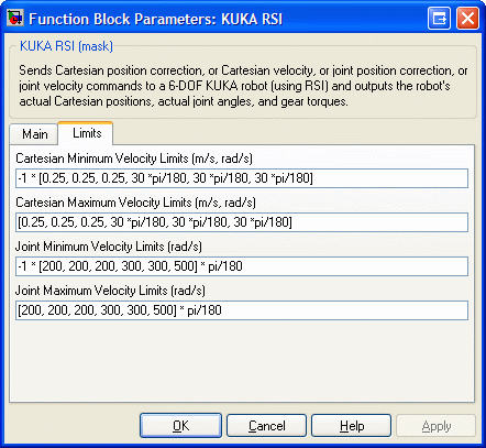
Cartesian Minimum Velocity Limits (m/s, rad/s)
A 6-element vector containing the minimum velocity limits (in m/s and rad/s) for each Cartesian axis of the robot. These limits low saturate the Cartesian velocity commands sent to the robot and are effective when one of the two Cartesian control modes is selected.
Cartesian Maximum Velocity Limits (m/s, rad/s)
A 6-element vector containing the maximum velocity limits (in m/s and rad/s) for each Cartesian axis of the robot. These limits high saturate the Cartesian velocity commands sent to the robot and are effective when one of the two Cartesian control modes is selected.
Joint Minimum Velocity Limits (rad/s)
A 6-element vector containing the minimum velocity limits (in rad/s) for each joint of the robot. These limits low saturate the joint velocity commands sent to the robot and are effective when one of the two joint control modes is selected.
Joint Maximum Velocity Limits (rad/s)
A 6-element vector containing the maximum velocity limits (in rad/s) for each joint of the robot. These limits high saturate the joint velocity commands sent to the robot and are effective when one of the two joint control modes is selected.
The table below indicates the KUKA KR 5 sixx R850 robot physical velocity limits for each joint.
|
Axis |
Velocity Limits |
|---|---|
|
Axis 1 |
±250°/s |
|
Axis 2 |
±250°/s |
|
Axis 3 |
±250°/s |
|
Axis 4 |
±410°/s |
|
Axis 5 |
±410°/s |
|
Axis 6 |
±660°/s |
The table below indicates the KUKA KR 5 sixx R850 robot absolute position range (software-limited) from each joint zero position.
|
Axis |
Position Range |
|---|---|
|
Axis 1 |
±170° |
|
Axis 2 |
+45° / -190° |
|
Axis 3 |
+169° / -119° |
|
Axis 4 |
±190° |
|
Axis 5 |
±120° |
|
Axis 6 |
±350° |
The table below indicates the KUKA KR 5 sixx R650 robot physical velocity limits for each joint.
|
Axis |
Velocity Limits |
|---|---|
|
Axis 1 |
±375°/s |
|
Axis 2 |
±300°/s |
|
Axis 3 |
±375°/s |
|
Axis 4 |
±410°/s |
|
Axis 5 |
±410°/s |
|
Axis 6 |
±660°/s |
The table below indicates the KUKA KR 5 sixx R650 robot absolute position range (software-limited) from each joint zero position.
|
Axis |
Position Range |
|---|---|
|
Axis 1 |
±170° |
|
Axis 2 |
+45° / -190° |
|
Axis 3 |
+166° / -119° |
|
Axis 4 |
±190° |
|
Axis 5 |
±120° |
|
Axis 6 |
±350° |
The table below indicates the KUKA KR 6-2 robot physical velocity limits for each joint.
|
Axis |
Velocity Limits |
|---|---|
|
Axis 1 |
±156°/s |
|
Axis 2 |
±156°/s |
|
Axis 3 |
±156°/s |
|
Axis 4 |
±343°/s |
|
Axis 5 |
±362°/s |
|
Axis 6 |
±659°/s |
The table below indicates the KUKA KR 16-2 robot physical velocity limits for each joint.
|
Axis |
Velocity Limits |
|---|---|
|
Axis 1 |
±156°/s |
|
Axis 2 |
±156°/s |
|
Axis 3 |
±156°/s |
|
Axis 4 |
±330°/s |
|
Axis 5 |
±330°/s |
|
Axis 6 |
±615°/s |
The table below indicates the KUKA KR 6-2 and KR 16-2 robots absolute position range (software-limited) from each joint zero position.
|
Axis |
Position Range |
|---|---|
|
Axis 1 |
±185° |
|
Axis 2 |
+35° / -155° |
|
Axis 3 |
+154° / -130° |
|
Axis 4 |
±350° |
|
Axis 5 |
±130° |
|
Axis 6 |
±350° |
Targets
|
Target Name |
Compatible* |
Model Referencing |
Comments |
|---|---|---|---|
|
Yes |
Yes |
||
|
Yes |
Yes |
||
|
No |
No |
||
|
No |
No |
||
|
No |
No |
||
|
No |
No |
||
|
No |
No |
||
|
No |
No |
||
|
No |
No |
||
|
No |
No |
||
|
No |
No |
||
|
No |
No |
||
|
No |
No |
||
|
No |
No |
Last fully supported in QUARC 2018. |
|
|
Rapid Simulation (RSIM) Target |
No |
No |
|
|
S-Function Target |
No |
N/A |
Old technology. Use model referencing instead. |
|
Normal simulation |
No |
No |
See Also

Copyright ©2025 Quanser Inc. This page was generated 2025-11-01. Submit feedback to Quanser about this page.
Link to this page.