
NI ELVIS III
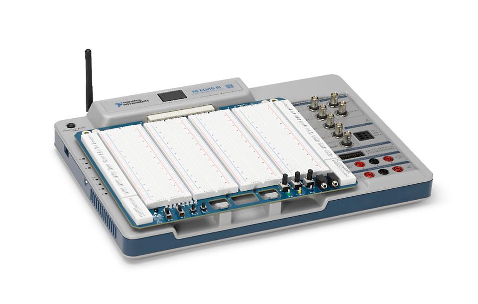
The NI ELVIS III is a National Instrument embedded device with real-time processing capability and a rich set of I/O. The QUARC Target associated with the NI ELVIS III is the QUARC Linux ARMv7 Target. The NI ELVIS III HIL card may only be used with QUARC when this target is selected. The following characteristics (using the default FPGA personality from National Instrument) are of particular interest when using the NI ELVIS III with QUARC:
The QUARC driver name for this card is ni_elvisiii.
To select the NI ELVIS III HIL board, select the QUARC ni_elvisiii board type from the drop-down list on the Main tab of the HIL Initialize block.
| Note that the Linux ARMv7 target must be selected to use the NI ELVIS III board. |
Communications
The communications ports provided on the NI ELVIS III HIL board can be utilized through the QUARC Communications blockset and the Quanser Stream API (see QUARC Communications Protocols).
For SPI communications, a sample URI for communications would be:
spi://localhost:0?baud='1000000',polarity='off',phase='off',lsb='off',frame='0'
where the frame option selects the SPI SS line to frame the SPI bus transaction (0 to 39 inclusive, except 5 to 7 and 25 to 27).
For I2C communications, a sample URI for communications would be:
i2c://localhost:0?baud='400000',address=0x69
where the address option specifies the I2C slave address.
For serial communications, a sample URI for communications would be:
serial://localhost:0?baud='115200',word='8',parity='none',stop='1'
where the options are standard serial port options 8-N-1 configuration on port 0.
Clocks
There are currently no configuration options for the NI ELVIS III clocks.
Analog Inputs
The NI ELVIS III supports 16 analog inputs with 16-bit resolution. Hence, analog input channel numbers range from 0 to 15.
The valid input ranges are ±10V, ±5V, ±2V, ±1V.
To change from the default range of ±10V, set the selected channels in the Analog Inputs
tab of the HIL Initialize block to the channels in use. For example, enter
0:1 to indicate channels 0 through 1. Specify [0] to indicate channel 0. Next set the analog input
maximum and minimum.
The supported analog input configurations are Referenced singled-ended (0), Differential (2).
In order to change the analog input configuration for the selected channels in the Analog Inputs tab of the
HIL Initialize , set the Analog input channels field to
the analog input channels on the board for the current diagram, and then set the Analog input configurations
field to the desired configuration. For example, enter [0 1 2] in the Analog input channels field and
[0 0 2] in the Analog input configurations field, to set channel 0 to referenced single-ended,
channel 1 to referenced single-ended, and channel 2 to differential.
Analog Outputs
The NI ELVIS III supports 4 analog output with 16-bit resolution. Hence, analog input channel numbers range from 0 to 3.
The only valid output range is ±10V.
In order to have analog outputs set to a particular voltage when the model is loaded
or unloaded, the analog outputs must be configured on the
HIL Initialize block's Analog Outputs tab. Set the
Analog output channels field to all the analog output channels that will be
used on the board for the current diagram. For example, enter 1:3 to indicate channels 1
through 3. Specify [0, 2, 7] to indicate channels 0, 2 and 7.
Digital Inputs
The NI ELVIS III supports 40 bidirectional digital I/O lines and one special digital input lines. Hence digital input channel numbers range from 0 to 40. Channel 40 represents the On board button.
A bidirectional digital I/O line cannobe be used as an input and output at the same time.
Since the digital I/O lines may be individually programmed as inputs or outputs, all the channels which will
be used for digital inputs should be configured on the HIL Initialize
block's Digital Inputs tab. Set the Digital input channels field to all
the digital I/O channels that will be used as digital inputs on the board for the current diagram. For example,
enter 2:5 to designate lines 2 through 5 as digital inputs. Specify [0, 4, 5] to indicate that
lines 0, 4 and 5 are to be configured as digital inputs.
Despite the fact that this card has dedicated digital input lines, you still need to configure all the channels which will be used
as digital inputs. They should be configured on the HIL Initialize
block's Digital Inputs tab. Set the Digital Input channels
field to all the digital input channels that will be used for the current diagram. For example, enter 0:3 to designate
lines 0 through 3. Specify [0, 2] to indicate that lines 0 and 2 are to be used in the current diagram.
 Note that the bidirectional digital I/O lines can also be configured as PWM, encoder, SPI, I2C, or serial I/O. All of these I/O have
precedent over the digital input or output functions. Therefore if the pin is configured as one of the other functions, the digital
input or output functions would no longer function. Refer to Board-specific options for more
details about how to configure all these functions that share the same pin.
Note that the bidirectional digital I/O lines can also be configured as PWM, encoder, SPI, I2C, or serial I/O. All of these I/O have
precedent over the digital input or output functions. Therefore if the pin is configured as one of the other functions, the digital
input or output functions would no longer function. Refer to Board-specific options for more
details about how to configure all these functions that share the same pin.
Digital Outputs
The NI ELVIS III supports 40 bidirectional digital I/O lines and 4 special digital output lines. Hence digital input channel numbers range from 0 to 43. Channels 40 to 43 represents the On board LED0 to LED3.
A bidirectional digital I/O line cannobe be used as an input and output at the same time.
Since the digital I/O lines may be individually programmed as inputs or outputs, all the channels which will
be used for digital outputs should be configured on the HIL Initialize
block's Digital Outputs tab. Set the Digital output channels field to all
the digital I/O channels that will be used as digital outputs on the board for the current diagram. For example,
enter 2:5 to designate lines 2 through 5 as digital outputs. Specify [0, 4, 5] to indicate that
lines 0, 4 and 5 are to be configured as digital outputs.
Despite the fact that this card has dedicated digital output lines, you still need to configure all the channels which will be used
as digital outputs. They should be configured on the HIL Initialize
block's Digital Outputs tab. Set the Digital Output channels
field to all the digital output channels that will be used for the current diagram. For example, enter 0:3 to designate
lines 0 through 3. Specify [0, 2] to indicate that lines 0 and 2 are to be used in the current diagram.
To set the digital output values when the model is loaded or unloaded, set the Initial digital outputs and Final digital outputs to the desired values respectively. If the vectors specified in these fields are shorter than the channel vector, the value of the last element in the vector will be used for the rest of the channels. Hence, a scalar value will apply to all channels specified in the Digital output channels field.
Note that the bidirectional digital I/O lines can also be configured as PWM, encoder, SPI, I2C, or serial I/O. All of these I/O have
precedent over the digital input or output functions. Therefore if the pin is configured as one of the other functions, the digital
input or output functions would no longer function. Refer to Board-specific options for more
details about how to configure all these functions that share the same pin.
Encoder Inputs
The NI ELVIS III supports 20 encoder inputs. Hence encoder channel numbers range from 0 to 19. These channels support non-quadrature as well as 4x quadrature modes.
In order to set the encoder counters to a particular count or to change the default
quadrature when the model is loaded, the encoder inputs must
be configured on the HIL Initialize
block's Encoder Inputs tab. Set the Encoder input channels
field to all the encoder channels that will be
used on the board for the current diagram. For example, enter
0:1
to
indicate channels 0 through 1 are used as encoder inputs.
The NI ELVIS III supports non-quadrature (count and direction) and 4X quadrature. Since the NI ELVIS III has 32-bit counters, valid initial count values range from -2147483648 to +2147483647. If the vectors specified in these fields are shorter than the channel vector, the value of the last element in the vector will be used for the rest of the channels. Hence, a scalar value will apply to all channels specified in the Encoder input channels field.
Note that the bidirectional digital I/O lines can also be configured as PWM, encoder, SPI, I2C, or serial I/O. All of these I/O have
precedent over the digital input or output functions. Therefore if the pin is configured as one of the other functions, the digital
input or output functions would no longer function. Refer to Board-specific options for more
details about how to configure all these functions that share the same pin.
PWM Outputs
The NI ELVIS III driver supports 40 PWM output channels. Hence, PWM output channels range from 0 to 39. Each PWM channel is completely independent and can have its own duty cycle and frequency.
In order to configure the PWM mode or frequency, or to set the value of the PWM outputs when the model is loaded or unloaded, the PWM
outputs must be configured on the HIL Initialize block's
PWM Outputs tab. Set the PWM output channels field to all the PWM output channels that will be used on the
board for the current diagram. For example, enter 0:1 to indicate channels 0 and 1. Specify 1 to indicate channel 1 alone.
The maximum output frequency is 20 MHz. The number of bits of resolution decreases with increasing PWM output frequency.
For a complete description of all the options available, including diagrams, refer to PWM Output Configurations.
Note that the bidirectional digital I/O lines can also be configured as PWM, encoder, SPI, I2C, or serial I/O. All of these I/O have
precedent over the digital input or output functions. Therefore if the pin is configured as one of the other functions, the digital
input or output functions would no longer function. Refer to Board-specific options for more
details about how to configure all these functions that share the same pin.
Other Inputs
The NI ELVIS III card does not support other inputs.
Other Outputs
The NI ELVIS III card does not support other outputs.
Interrupts
The NI ELVIS III card, or its driver, does not support any interrupt sources.
Watchdog
The NI ELVIS III card does not support a watchdog timer.
Board-Specific Options
The NI ELVIS III has a number of board-specific options to control specialized functionality of the card. These options control which functions to enable on the bidirectional digital I/O lines.
Due to the large number of bidirectional digital I/O lines, it is recommended to use board-specific options dialog to set the board-specific options instead of typing them in manually. The dialog also has option to automatically update the Encoder input channels and PWM output channels in the Encoder Inputs and PWM Outputs tabs, respectively once the particular function is selected for a channel.
Furthermore the board-specific options dialog also has an option to enable National Instrument naming convention (e.g. Bank B0 instead of Channel 20) for each channel to allow easier channel selection for users who are more accustomed to National Instrument naming conventions.
pwm0_en
Set this option to "yes", "y", or "1" to enable the PWM functionality on bidirectional digital I/O pin number 0.
Similar options exist for the other PWM channels e.g. pwm1_en, pwm2_en, etc.
enc0_en
Set this option to "yes", "y", or "1" to enable the encoder functionality on bidirectional digital I/O pin number 0 and 1.
Similar options exist for the other encoder channels e.g. enc1_en, enc2_en, etc.
enc0_dir
Set this option to "yes", "y", or "1" to reverse the direction of encoder 0.
Similar options exist for the other encoder channels e.g. enc1_dir, enc2_dir, etc.
Properties
The NI ELVIS III card does not support any properties.
Connectors
The NI ELVIS III board has many different I/Os, and some of them even support multiple functions. The following connectors show the possible pin functions on the NI ELVIS III SERIES PROTOTYPE BOARD on the left-hand side for reference and the Quanser channel numbers on the right-hand side.
Bank A
NI Label | Functions/Channels | |
AI0 → | ▣ | ← AI 0 |
AI1 → | ▣ | ← AI 1 |
AI2 → | ▣ | ← AI 2 |
AI3 → | ▣ | ← AI 3 |
AI4 → | ▣ | ← AI 4 |
AI5 → | ▣ | ← AI 5 |
AI6 → | ▣ | ← AI 6 |
AI7 → | ▣ | ← AI 7 |
AGND ― | ▣ | ― AGND |
― | ― | |
AO0 ← | ▣ | → AO 0 |
AO1 ← | ▣ | → AO 1 |
AGND ― | ▣ | ― AGND |
― | ― | |
+15V ― | ▣ | ― +15V |
-15V ― | ▣ | ― -15V |
DGND ― | ▣ | ― DGND |
+5V ― | ▣ | ― +5V |
DGND ― | ▣ | ― DGND |
― | ― | |
DIO0 ↔ | ▣ | ↔ DIO 0 / → PWM 0 / ← ENC.A 0 |
DIO1 ↔ | ▣ | ↔ DIO 1 / → PWM 1 / ← ENC.B 0 |
DIO2 ↔ | ▣ | ↔ DIO 2 / → PWM 2 / ← ENC.A 1 |
DIO3 ↔ | ▣ | ↔ DIO 3 / → PWM 3 / ← ENC.B 1 |
DGND ― | ▣ | ― DGND |
+3.3V ― | ▣ | ― +3.3V |
― | ― | |
DIO4 ↔ | ▣ | ↔ DIO 4 / → PWM 4 / ← ENC.A 2 |
DIO5 ↔ | ▣ | ↔ DIO 5 / → PWM 5 / ← ENC.B 2 / → SPI.CLK 0 |
DIO6 ↔ | ▣ | ↔ DIO 6 / → PWM 6 / ← ENC.A 3 / ← SPI.MISO 0 |
DIO7 ↔ | ▣ | ↔ DIO 7 / → PWM 7 / ← ENC.B 3 / → SPI.MOSI 0 |
DGND ― | ▣ | ― DGND |
+3.3V ― | ▣ | ― +3.3V |
― | ― | |
DIO8 ↔ | ▣ | ↔ DIO 8 / → PWM 8 / ← ENC.A 4 |
DIO9 ↔ | ▣ | ↔ DIO 9 / → PWM 9 / ← ENC.B 4 |
DIO10 ↔ | ▣ | ↔ DIO 10 / → PWM 10 / ← ENC.A 5 |
DIO11 ↔ | ▣ | ↔ DIO 11 / → PWM 11 / ← ENC.B 5 |
DGND ― | ▣ | ― DGND |
+3.3V ― | ▣ | ― +3.3V |
― | ― | |
DIO12 ↔ | ▣ | ↔ DIO 12 / → PWM 12 / ← ENC.A 6 |
DIO13 ↔ | ▣ | ↔ DIO 13 / → PWM 13 / ← ENC.B 6 |
DIO14 ↔ | ▣ | ↔ DIO 14 / → PWM 14 / ← ENC.A 7 / ↔ I2C.SCL 0 |
DIO15 ↔ | ▣ | ↔ DIO 15 / → PWM 15 / ← ENC.B 7 / ↔ I2C.SDA 0 |
DGND ― | ▣ | ― DGND |
+3.3V ― | ▣ | ― +3.3V |
― | ― | |
DIO16 ↔ | ▣ | ↔ DIO 16 / → PWM 16 / ← ENC.A 8 / ← UART.RX 0 |
DIO17 ↔ | ▣ | ↔ DIO 17 / → PWM 17 / ← ENC.B 8 / → UART.TX 0 |
DIO18 ↔ | ▣ | ↔ DIO 18 / → PWM 18 / ← ENC.A 9 |
DIO19 ↔ | ▣ | ↔ DIO 19 / → PWM 19 / ← ENC.B 9 |
DGND ― | ▣ | ― DGND |
+3.3V ― | ▣ | ― +3.3V |
Bank B
NI Label | Functions/Channels | |
AI0 → | ▣ | ← AI 8 |
AI1 → | ▣ | ← AI 9 |
AI2 → | ▣ | ← AI 10 |
AI3 → | ▣ | ← AI 11 |
AI4 → | ▣ | ← AI 12 |
AI5 → | ▣ | ← AI 13 |
AI6 → | ▣ | ← AI 14 |
AI7 → | ▣ | ← AI 15 |
AGND ― | ▣ | ― AGND |
― | ― | |
AO0 ← | ▣ | → AO 2 |
AO1 ← | ▣ | → AO 3 |
AGND ― | ▣ | ― AGND |
― | ― | |
+15V ― | ▣ | ― +15V |
-15V ― | ▣ | ― -15V |
DGND ― | ▣ | ― DGND |
+5V ― | ▣ | ― +5V |
DGND ― | ▣ | ― DGND |
― | ― | |
DIO0 ↔ | ▣ | ↔ DIO 20 / → PWM 20 / ← ENC.A 10 |
DIO1 ↔ | ▣ | ↔ DIO 21 / → PWM 21 / ← ENC.B 10 |
DIO2 ↔ | ▣ | ↔ DIO 22 / → PWM 22 / ← ENC.A 11 |
DIO3 ↔ | ▣ | ↔ DIO 23 / → PWM 23 / ← ENC.B 11 |
DGND ― | ▣ | ― DGND |
+3.3V ― | ▣ | ― +3.3V |
― | ― | |
DIO4 ↔ | ▣ | ↔ DIO 24 / → PWM 24 / ← ENC.A 12 |
DIO5 ↔ | ▣ | ↔ DIO 25 / → PWM 25 / ← ENC.B 12 / → SPI.CLK 1 |
DIO6 ↔ | ▣ | ↔ DIO 26 / → PWM 26 / ← ENC.A 13 / ← SPI.MISO 1 |
DIO7 ↔ | ▣ | ↔ DIO 27 / → PWM 27 / ← ENC.B 13 / → SPI.MOSI 1 |
DGND ― | ▣ | ― DGND |
+3.3V ― | ▣ | ― +3.3V |
― | ― | |
DIO8 ↔ | ▣ | ↔ DIO 28 / → PWM 28 / ← ENC.A 14 |
DIO9 ↔ | ▣ | ↔ DIO 29 / → PWM 29 / ← ENC.B 14 |
DIO10 ↔ | ▣ | ↔ DIO 30 / → PWM 30 / ← ENC.A 15 |
DIO11 ↔ | ▣ | ↔ DIO 31 / → PWM 31 / ← ENC.B 15 |
DGND ― | ▣ | ― DGND |
+3.3V ― | ▣ | ― +3.3V |
― | ― | |
DIO12 ↔ | ▣ | ↔ DIO 32 / → PWM 32 / ← ENC.A 16 |
DIO13 ↔ | ▣ | ↔ DIO 33 / → PWM 33 / ← ENC.B 16 |
DIO14 ↔ | ▣ | ↔ DIO 34 / → PWM 34 / ← ENC.A 17 / ↔ I2C.SCL 1 |
DIO15 ↔ | ▣ | ↔ DIO 35 / → PWM 35 / ← ENC.B 17 / ↔ I2C.SDA 1 |
DGND ― | ▣ | ― DGND |
+3.3V ― | ▣ | ― +3.3V |
― | ― | |
DIO16 ↔ | ▣ | ↔ DIO 36 / → PWM 36 / ← ENC.A 18 / ← UART.RX 1 |
DIO17 ↔ | ▣ | ↔ DIO 37 / → PWM 37 / ← ENC.B 18 / → UART.TX 1 |
DIO18 ↔ | ▣ | ↔ DIO 38 / → PWM 38 / ← ENC.A 19 |
DIO19 ↔ | ▣ | ↔ DIO 39 / → PWM 39 / ← ENC.B 19 |
DGND ― | ▣ | ― DGND |
+3.3V ― | ▣ | ― +3.3V |
Legend
→▯← | = | input |
←▯→ | = | output |
↔▯↔ | = | bidirectional I/O |
= | 3.3V signal | |
= | unspecified voltage | |
= | power | |
= | ground |
Targets
|
Target |
Supported |
Comments |
|---|---|---|
|
No |
Not supported. |
|
|
No |
Not supported. |
|
|
No |
Not supported. |
|
|
No |
Not supported. |
|
|
No |
Not supported. |
|
|
No |
Not supported. |
|
|
No |
Not supported. |
|
|
No |
Not supported. |
|
|
No |
Not supported. |
|
|
Yes |
Only supported with an ELVIS III platform. |
|
|
No |
Not supported. |
|
|
No |
Not supported. |
|
|
No |
Not supported. |
|
|
No |
Not supported. |
|
|
No |
Not supported. |
|
|
Rapid Simulation (RSIM) Target |
No |
Not supported. |
|
Normal simulation |
No |
Not supported. |
See Also
Copyright ©2026 Quanser Inc. This page was generated 2026-05-13. Submit feedback to Quanser about this page.
Link to this page.