MATLAB Command Line
Click to copy the following command line to the clipboard. Then paste it in the MATLAB Command Window:
quarc_network_latency_measurement_server_demo; quarc_network_latency_measurement_client_demoQUARC Network Latency Measurement Demo
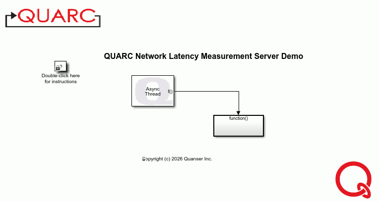
This example consists of two Simulink models: a server and a client. The client sends a packet containing one byte to the server, and the server echoes it back. The client measures the exact round-trip time for the packet to be sent and the echo to be received. The example uses the Advanced Communications blocks in an asynchronous thread, so the measurement is independent of the sample time of the two models. Indeed, the measured latency is likely to be less than the sample time. For a detailed description of the Advanced Communications blockset from the QUARC Targets Library and how they operate, please refer to the Advanced Communications - Blocking Mode section of the QUARC documentation. For general information on the Advanced Communications feature of QUARC, you can refer to the Advanced Communications section.
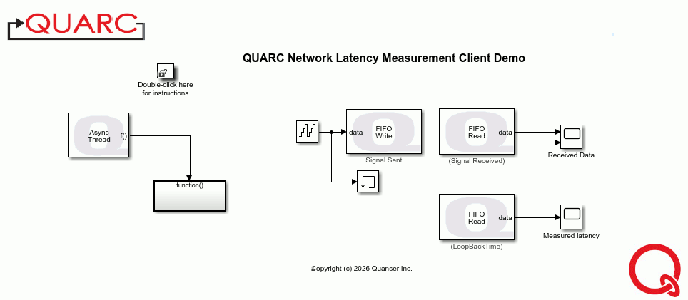
The client model plots the measured latency as well as the value sent and the value received. A Memory block is used to add a one sample delay to the value sent because the the value received will be read from the FIFO on the next sampling instant. The plot of the values sent and received is only a crude indication of the latency - the measured latency plot shows the actual latency. For instance, the sample time of the client is 1 ms. But if the latency is 1.5 ms then the response from the server will not be shown until two sampling instants later, making it look like the latency is 1 ms (recall the Memory block). However, the measured latency plot will show the actual latency of 1.5 ms.
Using a protocol other than TCP/IP (such as UDP) or sending larger packets is possible but requires minor changes to each model, as explained below. Note that on desktop operating systems, like Windows, network latency measurements can be affected by other processes on the system, such as DMA and interrupts from other devices. Hence, the most reliable latency measurements are obtained using embedded platforms.
To ensure the client model does not send packets faster than the network latency can support, this model slows down its sample time by using a blocking write to the FIFO Write (Signal Sent) block. Hence, it should not be used as an example for general communications.
Configuring the Demonstration
To set up the demonstration, double-click on the "Function-Call" subsystem in the quarc_network_latency_measurement_server_demo.mdl model. Next, double-click on the Stream Listen block. Also, double-click on the "Function-Call" subsystem in the quarc_network_latency_measurement_client_demo.mdl model. Next, double-click on the Stream Connect block. Now, make sure the URI upon which to listen parameter of Stream Listen block is the same as the URI of host to which to connect parameter of the Stream Connect block.
If the client and server are run on different machines then set the URI of the Stream Connect block on the client to use the IP address or hostname of the server's machine. For example, if the server is using TCP/IP on a machine with IP address 192.168.111.100 then the URI on both client and server should be "tcpip://192.168.111.100:18000?nagle=0", assuming port 18000 will be used. The nagle option of 0 disables the Nagle algorithm because Nagle optimizes network bandwidth at the expense of latency.
The URI is also the place to change the protocol, if desired. For instance, to use UDP instead of TCP/IP in the example above, use a URI of "udp://192.168.111.100:18000". UDP does not use the Nagle algorithm. Since UDP has lower overhead than TCP/IP, better network latency should be expected from UDP.
If a one byte packet is sufficient for the network latency measurement then skip the next section and go straight to Building, deploying and starting the models below.
Configuring the Packet
Changing the packet size is a little more complicated. For the quarc_network_latency_measurement_client_demo.mdl model, change the Counter Free-Running source block to the desired signal. For example, suppose a Sine Wave is used, which outputs a scalar double signal. Double-click on the FIFO Write block for the Signal Sent and click on the button. Double-click on the FIFO Read block for the the Signal Sent and go to the Signal Data Types tab. Change the Data output data type option to double because our signal is now a double. If a vector signal is used then also change the Default value parameter on the Main tab to a vector of the same size.
Now double-click on the triggered Subsystem on the same page. Inside that subsystem, double click on the Stream Receive block and change the Output data type parameter to double, again because our signal is now a double. If a vector signal is used, then also change the Dimensions parameter to reflect the number of elements in that vector.
This completes the changes for the client model.
For the quarc_network_latency_measurement_server_demo.mdl model, double-click on the Function-Call Subsystem. Then double-click on the Enabled Subsystem to go down one level. Then double-click on the While Iterator Subsystem to drill down one more level. Then double-click on the Enabled Subsystem and then on the While Iterator Subsystem. Finally, double-click on the Stream Receive block. Change the Output data type parameter to double, because our signal is now a double. If a vector signal is used, then also change the Dimensions parameter to reflect the number of elements in that vector.
This completes the changes for the server model.
Demonstration
Building, deploying and starting the models
Refer to One Step Process in QUARC Basic Procedures to build, deploy and start each model.
Note that the order in which you start the models is not important. However, in practical situations, the server side should always be running before the client starts.
 In the case of using UDP as the communication protocol, it's necessary to start the server prior to the client. The reason is UDP does not
establish a connection between client and server, and the server relies on the IP address of its received packets to communicate. When the client
is started, it sends a data packet to the server, and because of its blocking design, it waits for a reply from the server which has
not been started yet. On the other hand, when the server is started, it waits for a packet from the client to know the IP address of the client.
Therefore, both parties wait for each other, and no data is communicated.
In the case of using UDP as the communication protocol, it's necessary to start the server prior to the client. The reason is UDP does not
establish a connection between client and server, and the server relies on the IP address of its received packets to communicate. When the client
is started, it sends a data packet to the server, and because of its blocking design, it waits for a reply from the server which has
not been started yet. On the other hand, when the server is started, it waits for a packet from the client to know the IP address of the client.
Therefore, both parties wait for each other, and no data is communicated.
This problem can be solved when the client is running on Windows. The solution is to add in front of the client URI. In this case, when the server is unreachable an error signal is created internally, and the client tries to send the starting data packet again. Therefore, when the server is started, it eventually receives a data packet from the client, making it leave its listening state, and start the communication.
Running the model
Double-click on the "Received Data" Scope in the quarc_network_latency_measurement_client_demo.mdl model to open the Scope showing the received data. Double-click on the "Measured latency" Scope to open the Scope showing the actual measured latency.
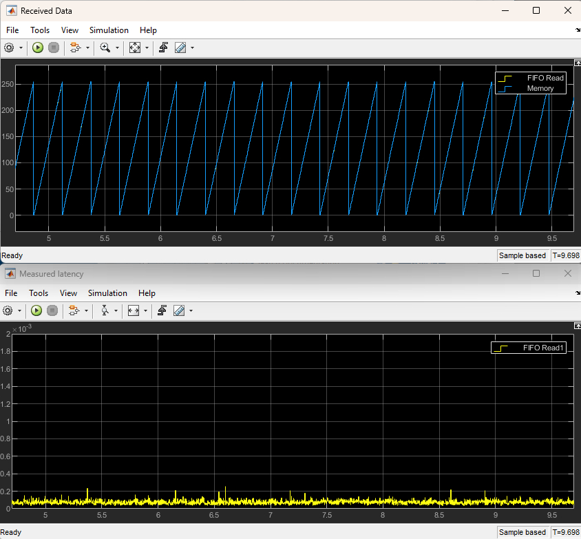
If the source block has not been reconfigured then two repeating sawtooth waves of sampling 255 will appear in the "Received Data" Scope. Hopefully, the network latency is low and the two curves will overlap each other. The yellow curve is the signal received and the blue curve is the signal sent. The actual network latency will be shown on the "Measured Latency" Scope. Sample plots are shown below when the client and server were run on the same machine (so the latency is understandably very low):
Stopping the models
Refer to One Step Process in QUARC Basic Procedures to stop each model.
Running the example on a different target
To run the example on a different target, refer to the instructions on the Running QUARC Examples on Remote Targets page.
If the quarc_network_latency_measurement_server_demo.mdl and the quarc_network_latency_measurement_client_demo.mdl model are being run on different targets, then the URI of the Stream Connect block in the client model should use the host name or IP address of the machine running the server for the hostname of its URI. For example, if the server is running on a machine with IP address 192.168.0.16 and the URI of the Stream Listen block in the server model is tcpip://localhost:18000?nagle='0', then the URI of the Stream Connect block in the client model should be tcpip://192.168.0.16:18000?nagle='0'. The server model could also use the same IP address instead of localhost.
Copyright ©2026 Quanser Inc. This page was generated 2026-05-13. Submit feedback to Quanser about this page.
Link to this page.