

Advanced Communications
The Advanced communications blockset may be found under the QUARC Targets/Communications/Advanced library in the Simulink Library Browser. This blockset includes the following blocks; Stream Connect, Stream Listen, Stream Accept, Stream Close, Stream Poll, Stream Send, Stream Flush, Stream Receive and Stream Print. The advanced communications blocks provide the full flexibility of the QUARC communications framework but are lower-level blocks that require a more sophisticated knowledge of communications than the other two types of communications blocks (Basic and Intermediate). The advanced blocks support two modes: blocking and non-blocking.
In blocking mode, the blocks do not return until the operation requested is complete. As such, blocking mode is typically used in an asynchronous thread running at a lower priority than the main diagram, so that the blocking I/O does not interfere with the sample time performance of the main diagram. In non-blocking mode, the blocks always return immediately and may therefore be used in the main diagram without compromising sample time performance. However, a simple state machine is generally required to keep track of when a connection is established and data may be transmitted or received. This section does not include any details about the blocks in the Advanced communications blockset, but rather provides an overview of how to use them to establish a connection between two models. Both blocking and non-blocking modes are discussed. Therefore, it is highly recommended that the user refers to these blocks' reference pages by using the Advanced Communications Blocks section.
Please use the following list to refer to each topic:
Advanced Communications - Blocking Mode
One of the operating modes of the Advanced communications blocks is the blocking mode. In this mode, as mentioned earlier, blocks do not return until the requested operation is complete. Therefore, blocking mode is usually used in an asynchronous thread running at a lower priority so that the blocking I/O does not interfere with the sample time performance of the main diagram. For information on asynchronous threads and how to create them, please refer to the Asynchronous Threads section of the QUARC documentation.
There are only two blocks in the blockset that have the option of switching modes between blocking and non-blocking, namely Stream Listen and Stream Connect. The first block is intended to be used on the server side and listens for connections from clients, while the other block may be used on the client side to establish a connection to a server. There is a parameter in the block parameters dialog for both of these blocks called Non-blocking. If this option is checked, then these blocks use non-blocking mode; otherwise they use blocking mode. By default, this option is not enabled so that blocking mode is used. The mode established by the Stream Listen or Stream Connect block determines the operating mode of all the other Advanced communications blocks that use the stream output by these two blocks. In other words, if the Stream Listen block is set to be non-blocking, other blocks connected to this block using its stm output port will also be non-blocking. The same rule applies to the blocks connected to the Stream Connect block.
Two sample models are used in this section to demonstrate how to use the Advanced communications blocks in blocking mode for establishing a connection between two models. Please refer to the QUARC Advanced Communications Demo - Blocking Mode MATLAB Command Line Click to copy the following command line to the clipboard. Then paste it in the MATLAB Command Window: matlab: helpview(fullfile(qc_root, 'quarcdemos', 'html', 'quarc_advanced_communications_blocking_demo.html')) reference page in the MATLAB Demo section to open these models.
The first model is called "quarc_advanced_blocking_server" and is the model acting as the server. The second model is called "quarc_advanced_blocking_client" and acts as a client. The "quarc_advanced_blocking_client" model connects to the "quarc_advanced_blocking_server" model and sends data (sine wave) to it. The server model, in turn, sends the received data back to the client model. These two models comprise a communications loopback system.
Server Model
The following figure depicts the "quarc_advanced_blocking_server" model.
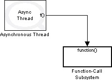
An Asynchronous Thread block is present to create an asynchronous thread. The Asynchronous Thread block executes the Function Call Subsystem block attached to its output in an asynchronous thread. The Priority parameter is set to 5. In general, asynchronous threads are usually executed at a lower priority than the main diagram (whose priority is 2 with external mode enabled), but in this example there is no code in the main diagram so the priority of the asynchronous thread has been boosted to 5 to avoid interface by the external mode communications, which run in separate threads at priority 0 and 1. The server model is configured to run at a fundamental sample time of only 1 second (1 Hz) by setting the Fixed-step size parameter in the Solver pane of the Configuration Parameters dialog to 1. The client model (explained later) will be running at 1 kHz or 1 millisecond. The client sends data at 1 kHz, but the server is running at 1 Hz. The server model can keep up with the data transfer rate of the client model because the communications is done in an asynchronous thread. As we will see, the server responds as soon as data arrives - independent of the sample time of the main diagram. This immediate response is actually the key advantage of using blocking mode in asynchronous threads. You do not have to worry about the models' rates. The asynchronous threads are aperiodic and receive data the moment it becomes available and send data as soon as it is ready, rather than sending/receiving data at each sampling instant only.
The other important parameter in the Asynchronous Thread
block parameters dialog is the Asynchronous mode. The mode
is set to one-shot so that the asynchronous thread is started
once at the beginning of the run, and never again. This way, the server thread gets
created, starts listening for connections in a while loop (explained later) and
never exits. If any errors occur while the server is running, the operation stops
and the thread exits and will never be created again unless you restart the model.
For more information about the one-shot asynchronous mode in addition to this block's
details in general, refer to the
Asynchronous Thread block's reference page.
The figure below illustrates the contents of the Function Call Subsystem block.
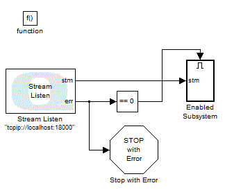
And the figure below illustrates the contents of the Enabled Subsystem block.

The above two consist of the top-level diagram for the server thread. The Stream Listen
block listens for connections on the URI specified in its block parameters dialog. In our
example, the URI upon which it listens is tcpip://localhost:18000, which causes it to
use the TCP/IP protocol to listen on localhost at port number 18000. This block creates
a listening stream every time it executes and outputs the listening stream to its
stm output port. For more information about this block, please refer
to the Stream Listen block
reference page. Since we are using blocking mode, the listening stream is blocking and makes
every other block which uses the stream also use blocking mode. Listening streams do not represent
a connection to a client. They cannot be used to send and receive data. A listening stream may only
be used by the Stream Accept block to accept a connection from a client. The
Stream Accept block will then output a stream that represents the connection
to the client and may be used to send or receive data over that connection.
The listening stream, in our case, is fed as an input into the While Iterator Subsystem
block which contains the Stream Accept block. This subsystem is basically a while loop
which accepts new connections and runs forever unless an error occurs accepting a connection, which causes
the loop to exit. The other input of the While Iterator Subsystem block is a constant
value of 1 connected to the IC input port. It represents the initial condition used by
the While Iterator block inside the While Iterator Subsystem block.
The only output of this subsystem is the listening stream propagated through the Stream Accept
block inside the loop. If any error occurs while accepting a new connection, the while loop exits and the listening
stream is returned and should be closed (since there is no use for it anymore) using the Stream Close
block. For details on this block, please refer to the Stream Close
block's reference page. If any errors occur while trying to create the listening stream itself, the model stops running using
the Stop with Error block found in the
QUARC Targets/Sinks library, which displays an error message corresponding to the error code in addition
to stopping the model. The only important parameter for this block is the Message type, which is set
to Interpret input as error code. For information about this block, refer to the
Stop with Error block's reference page.
The next figure illustrates the contents of the While Iterator Subsystem block. As mentioned earlier, this subsystem runs in a loop indefinitely, accepting a new connection from a client model each time around the loop.
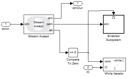
And the figure below illustrates the contents of the Enabled Subsystem block.

The Stream Accept block accepts new connections using the listening stream passed to it by the Stream Listen block. Since this stream is blocking, Stream Accept block creates a blocking connection to the client once a connection is accepted. Also, the block does not return until a new connection is actually accepted, since the listening stream is blocking. Once a connection is accepted, the block outputs a new stream representing the client connection at its cstm output port. The other Advanced communications blocks may then use this stream to exchange data with the client over the connection. The size of the send and receive buffers for the stream are specified in the block parameters dialog for the Stream Accept block. In our case, both send and receive buffer sizes are 8000 bytes. The block also outputs the listening stream at its stm output port. The listening stream, in case of errors, is output by the while loop to be closed by the Stream Close block i
After the connection is accepted, the corresponding stream it is fed into another While Iterator Subsystem. This nested while loop receives data from the client and sends it back to the client using this stream. A constant value of 1 is also fed into this second While Iterator Subsystem block to be used as the while loop's initial condition. In the event of an error while receiving or sending data inside the nested while loop or the peer closing the connection, the while loop exits and returns the stream representing the connection through its stmOut output port to be closed by the Stream Close block.
The err output of the Stream Accept block
gets compared to zero and then fed into the While Iterator
block along with the IC input coming from the upper level diagram
(which is a constant value of 1). The While Iterator block is
configured to execute the while loop indefinitely by setting the Maximum number of iterations parameter to -1. This block checks the initial condition going
into its IC input port before executing the while
loop for the first time. If this input is true or 1, then the while
loop executes. The next time it tries to iterate around the loop, it checks the
cond input and if true, executes the loop. In our
case, the err output of the Stream Accept block is compared to zero, and the while loop is executed
for the next iteration only if there are no errors. The Stream Accept block outputs a negative error code when no connection is accepted
due to an error. This negative value makes the output of the Compare to Zero
block false, which in turn causes the While Iterator
block condition to become false. Thus, the while loop exits and the listening stream
gets returned to the upper level diagram to be closed by the Stream Close
in that subsystem.
The next figure illustrates the nested While Iterator Subsystem block contents. As discussed above, this subsystem is the loop in which data gets received from or sent to the client through the established connection.

The Stream Receive block receives data from the
client over the blocking stream representing the connection to the client. One of this block's parameters is called
Output data type which is set to double
in our case. Since the stream is blocking, the block will not output its received
data until a double (8 bytes) is received. Note that the data type is not verified
by the Stream Receive block and is not transmitted. If a 64-bit (8 byte) integer
is transmitted by the client, then those 8 bytes will be interpreted as a double,
resulting in a nonsensical value. However, in our example, the client model sends doubles so that the data types at
both ends of the connection are consistent.
If single was used as the output data type for this block, the block
would not return until 4 bytes worth of data were received. For more information
about this block, please refer to the
Stream Receive block's reference page.
The err output of the aforementioned block is 1 when new data of the specified size is received. In case of errors, this output becomes negative. This output is zero when the peer has closed the connection. The data output along with the stm output are fed into an Enabled Subsystem block in which the received data is sent back to the client, hence creating the loopback system mentioned earlier. The err output gets compared to zero, and then fed into this subsystem as the enable signal. This subsystem gets enabled only if the output from the Compare to Zero is true, which means that new data was received. Inside the subsystem, there is a Stream Send block along with a Stream Flush block. The outputs of this subsystem are stmOut, which is the stream forwarded by the Stream Flush block, and the error outputs from both of the included blocks. The stmOut output is returned by the while loop to the parent subsystem in case the connection is closed by the peer or an error occurs and the connection must be closed. The Stream Close block in parent subsystem closes the connection. The following figure depicts the contents of the Enabled Subsystem block.

The Stream Send block sends the data at its data input to the client. It actually writes the data to the stream send buffer first. The only time it actually flushes the send buffer to the underlying communication channel is when it is full. Since we have set the send buffer size to 8000 bytes and the data to be sent is 8 bytes in size, it would take a thousand iterations before this block would flush the buffer. To ensure that the data is sent immediately, the Stream Flush block is used to flush the stream send buffer, or in other words, to write the data from the stream send buffer to the underlying communication channel every time new data is present in the stream's send buffer. If the Stream Send block sends all the data successfully, it outputs an error value of 1. On the other hand, if it cannot send data to the stream buffer, it outputs a negative error code. If the Stream Flush manages to flush all the data in the buffer, it returns an error of value zero. If the connection is closed or an actual error occurs, this block returns a negative error output. For more information about these two blocks, please refer to the Stream Send and Stream Flush blocks' reference pages.
The err1 output coming from the Stream Send is compared to zero and if it is not positive (zero or negative)
then it causes the output of the Compare to Zero block to
become false. The other output port err2
coming from the Stream Flush block also gets compared
to zero and if negative, causes the output of the Compare to Zero block to become false. These two outputs, along with
the output of the Stream Receive block compared to zero, get fed into a Logical Operator
block which performs an AND operation on them. The result of this operation is fed
into the While Iterator block as its condition.
Thus, the while loop continues to iterate as long as no errors occur in the process
of receiving and sending data and as long as the peer keeps the connection open.
The parameters of this While Iterator block are
the same as the other While Iterator block. The
initial condition for this block is the constant value of 1 coming from the parent
subsystem.
Once the connection is closed or an error occurs, the nested while loop exits and returns the stream, which gets closed. The main while loop has now finished one iteration and goes back to the start of the loop, where the Stream Accept block gets executed and waits until a new client attempts to connect. Once a new connection is established, the whole process repeats. Thus, unless there is an error with the listening stream, the server keeps accepting new connections (the model stays in the main while loop).
Before explaining the details of the "quarc_advanced_blocking_client" model, it should be mentioned that with our server implementation, once a client connects to the server, no more clients can connect to it. By default, the new clients attempting to connect would wait some time until the waiting time for the protocol in use gets expired. At this point, they would give a timeout error and exit. You can change this behavior by queuing the waiting clients using the backlog option of URIs.
Client Model
The following figure illustrates the "quarc_advanced_blocking_client" model.

The sample time for this model is 1 kHz as mentioned earlier. An Asynchronous Thread block is present to execute the Function Call Subsystem attached to its output in an asynchronous thread. This thread is the main thread where the connection is made to the server. To avoid interference with the sample time of the main diagram, the Priority parameter for the asynchronous thread is set to zero - a lower priority than the main diagram. There is a FIFO Write block in the main diagram which writes its input data to a FIFO queue. The name of the queue is specified in the FIFO name parameter field of the block. In our case, the name of the FIFO queue is "Signal Sent". Data written to this queue is accessed in the asynchronous thread, where it gets sent to the server model. The reason for writing data (in our sample model, the data is a sine wave) into a FIFO queue rather than having the source block inside the asynchronous thread (inside the Function Call Subsystem block) is that the asynchronous thread is aperiodic and does not have a sample time, while the Sine Wave block is periodic and needs to be in the main diagram. The FIFO Write block is used to transfer data from the periodic main thread to the aperiodic asynchronous thread and vice versa. For more information about this block, please refer to the FIFO Write block's reference page.
The other block present in the main diagram is a FIFO Read block reading data from a FIFO queue named "Data Received". Data is written to this queue inside the asynchronous thread using a FIFO Write block. In general, for each queue, you need one FIFO Write block to write data and one FIFO Read block to read data. For more information about the latter block, please refer to the FIFO Read block's reference page. The next figure illustrates the contents of the Function Call subsystem block.
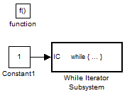
As shown in the above figure, the client model is actually placed in a while-loop, whose contents are shown in the following figure.
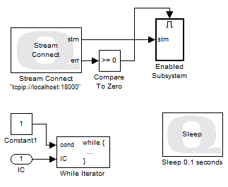
Please note that the Sleep block pauses the while-loop between connections to avoid an endless loop that uses 100% of the CPU time. The contents of While Iterator Subsystem block is shown in the figure below.
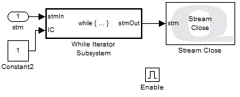
These two figures consist of the actual top-level diagram for the client thread. The Stream Connect block connects to a local or remote server using the URI specified
by the "URI of host to which to connect" parameter.
Since we want to connect to the "quarc_advanced_blocking_server" model, the URI here is the same
as the one used by that model to listen for connections, which is tcpip://localhost:18000.
The Non-blocking parameter should be unchecked
since we are using blocking mode. The Stream Connect
creates a blocking stream once the connection is established. The stream is passed
to the other Stream blocks through its stm output.
All the blocks using this stream will
also be blocking. The send/receive buffer sizes are set to 8000 bytes for the client
model in the Stream Connect block parameters dialog.
If there are any errors while trying to connect to the server, the err output will be negative and the model is stopped using the Stop with Error block, which displays a message corresponding to
the error code upon stopping the
model. The Message type parameter is set to
the same value as the one in the server model (Interpret input as error code).
For more information about these two blocks, please refer to the Stream Connect and
Stop with Error blocks' reference pages.
The stream created by the Stream Connect block is
fed into a While Iterator Subsystem block along
with a constant value of 1 as the initial condition. This subsystem is
the actual while loop in which sending and/or receiving of data take place. This
subsystem returns the stream once the loop is exited. The stream is then
closed by the Stream Close block since there is
no use for it anymore. For more information about this block, please refer to the
Stream Close block reference
page. The next figure depicts the contents of the While Iterator Subsystem block.

As mentioned before, this subsystem is the while loop in which data gets sent to the server and then received back from the server, hence creating the loopback system. The Stream Send block writes the data at its data input port into the stream's send buffer. Note that the data being fed into the block is coming from a FIFO Read block. The FIFO Read block is configured to wait for data to arrive in the queue before returning, so it will only return once the main diagram has written another data point into the FIFO queue. The FIFO queue from which data is obtained is called "Signal Sent", which contains the sine wave written to it in the main diagram. The Stream Flush block flushes data from the buffer to the underlying communication channel. The Stream Receive block then receives the data sent back to the client by the server and passes that data to a FIFO Write block. This block writes the received data into a FIFO queue called "Data Received". The queue is accessed in the main diagram using the FIFO Read block in that diagram. For more information about the Stream blocks used in this diagram, please refer to the Stream Send, Stream Flush and Stream Receive blocks' reference pages.
The err outputs of the Stream blocks are compared
to zero and then fed into a Logical Operator block
which performs an AND operation on them. The output of this block is then fed into
the While Iterator block as the condition for the
while loop. The initial condition of the block is the constant value of 1.
Therefore, the while loop gets executed the first time since the initial condition
is true. The next iterations of the while loop take place only if there are no errors
in sending, flushing or receiving data. The Maximum number of iterations parameter is set to -1 which indicates that
the while loop may iterate indefinitely. At the instant the while loop exits, the
Stream Receive block passes the stream to the parent
subsystem to be closed by the Stream Close block in that subsystem.
Once the models are created and built, you should first run the server and then the client model. In this example, the client is not designed to keep trying to connect if its first attempt fails, so if the client is started first then it will give an error and then exit because it cannot connect to the server. You can change the implementation to support persistent connections. After starting the models, the Scope block in the client model traces a sine wave as shown below.
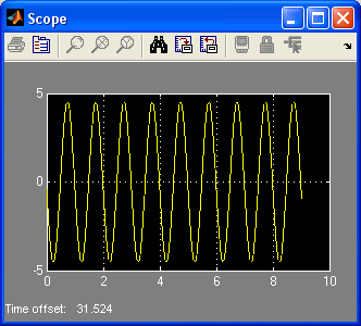
The fact that the scope traces a sine wave verifies that the connection was indeed established and the loopback operation has been performed correctly. If you look at the rate at which the scope plots data, you will notice that it is faster than the sample rate of the server model, which only runs at 1 Hz. The data is not decimated to 1 Hz. The reason the server is able to keep up with the 1 kHz data rate of the client model is because of the use of asynchronous threads. These threads do not have a sample time and thus the server sends data back to the client as soon as the data arrives, irrespective of the 1 Hz sample time of its main diagram. This ability of the advanced communications blocks in an asynchronous thread to respond immediately to the arrival of data over the connection is the primary advantage of this technique.
Another advantage of using blocking mode is that you can have any number of Stream Send or Stream Receive blocks in your model without having to worry about the order in which they send/receive data. You determine their execution order by daisy-chaining the blocks via their stream input and output ports. Each block executes in sequence and only returns when its operation is completed. This way, the succeeding blocks will not execute unless the preceding blocks have already completed their execution.
Another advantage of using blocking mode is that you can have any number of Stream Send or Stream Receive blocks in your model without having to worry about the order in which they send/receive data. You determine their execution order by daisy-chaining the blocks via their stream input and output ports. Each block executes in sequence and only returns when its operation is completed. This way, the succeeding blocks will not execute unless the preceding blocks have already completed their execution.
Advanced Communications - Non-Blocking Mode
Advanced communications can also be performed using non-blocking mode. In non-blocking mode, the blocks always return immediately and may therefore be used in the main diagram without compromising sample time performance. However, a simple state machine is generally required to keep track of when a connection is established and data may be transmitted or received.
There are only two blocks in the blockset that have the option of switching modes between blocking and non-blocking, namely Stream Listen and Stream Connect. The first block is intended to be used on the server side and listens for connections from clients while the other one may be used on the client side to establish a connection to a server. There is a parameter in the block parameters' dialog for both of these blocks called Non-blocking. If this option is checked, then non-blocking mode is used. Otherwise they use blocking mode. By default, this option is not enabled, so that blocking mode is used. To change the mode to non-blocking, check this option. Advanced communications blocks using the stream output by these blocks will use the same mode. In other words, if the Stream Listen block is set to be non-blocking, other blocks connected to this block using its stm output port will also be non-blocking. The same rule applies to blocks connected to the Stream Connect block.
Two sample models are used in this section to demonstrate how to use the Advanced communications blocks in non-blocking mode for establishing a connection between two models. Please refer to the QUARC Basic Communications Demo - Non-Blocking Mode MATLAB Command Line Click to copy the following command line to the clipboard. Then paste it in the MATLAB Command Window: matlab: helpview(fullfile(qc_root, 'quarcdemos', 'html', 'quarc_advanced_communications_nonblocking_demo.html')) reference page in the MATLAB Demo section to open these models.
The first model is called "quarc_advanced_nonblocking_server" and is the model acting as the server. The second model is called "quarc_advanced_nonblocking_client" and acts as a client. The "quarc_advanced_nonblocking_client" model connects to the "quarc_advanced_nonblocking_server"" model and sends a square wave to it. The server model, in turn, sends a sawtooth wave to the client model.
Server Model
The following figure depicts the "quarc_advanced_nonblocking_server" model.
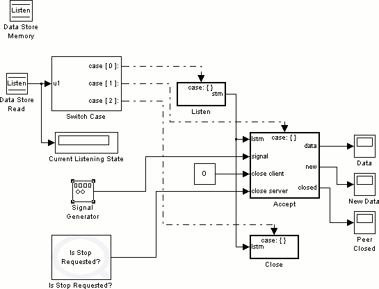
The main diagram contains a simple state machine to control the flow of program.
The Data Store Memory block at the top of the figure,
creates a global variable called "Listen" which is the listening state of the server.
This global variable is saved in a memory space and can be accessed by Data Store Read and Data Store Write
blocks for reading/writing purposes. The name of the variable is specified by the
Data store name parameter of the Data Store Memory block (in our case, it is set to Listen).
The Data Store Read reads the "Listen" variable
(listening state) and feeds it into a Switch Case
block. This block performs switching between different states based on the value
of the "Listen" variable. The "Listen" variable is fed into a display as well for
monitoring purposes.
There are three listening states available in our model. The first state is called "Listen" in which the server listens for new connections from clients. This state is specified by switch case 0. The second state is called "Accept" and is the state in which the server accepts connections from clients and handle the send/receive operations. This state contains another state machine inside which is explained later in this section. The switch case 1 is dedicated for the "Accept" state. The third state is called "Close" in which the listening stream created in the "Listen" state gets closed. Note that each of these states are implemented inside a Switch Case Action Subsystem block which is treated as an atomic unit by Simulink. If you look at the outputs of the Switch Case block, you will notice that they are connected to the action ports of the Switch case Action Subsystem blocks. For instance, the "Listen" state is switch case 0, hence case [0] output is fed into case: {} action port of the "Listen" state subsystem.
The listening stream created in the "Listen" state is fed into the other two states.
It is used in the "Accept" state by the Stream Accept
block to accept new connections. In the "Close" state, it is closed by the
Stream Close block. A Signal Generator
block generates the sawtooth wave which is to be sent to the client model. It feeds
its output to the "Accept" state subsystem where handling client connections and
sending/receiving data take place. A constant value of 0 is also fed
into this state's subsystem. You can force the client to close the connection by
changing this constant to 1. There is an Is Stop Requested block which feeds its output to the "Accept" state subsystem.
This block outputs a value of 1 if the model is stopped. It can be
used to close the listening stream upon server termination by the user. For more
information about this block, please refer to
Is Stop Requested block reference page. The "Accept" state subsystem outputs
new data received from the client side along with the new data flag indicating that
the data received are new and the flag indicating whether the peer has closed the
connection. These outputs are displayed on scopes for monitoring purposes. The next
figure illustrates the "Listen" state subsystem.
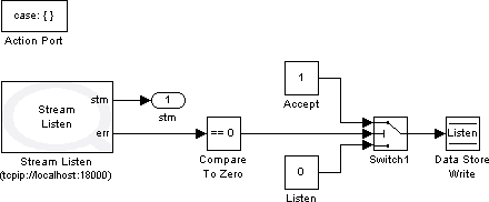
In this state, the server listens on a URI specified by the user for new connections,
as mentioned earlier. The Stream Listen block is
responsible for listening to new connections. The URI in this sample model is set
to tcpip://localhost:18000. The important parameter in this block's
parameters dialog is Non-blocking which should
be enabled to make the listening stream a non-blocking one. For more information
about this block, please refer to
Stream Listen block reference page. All the other Stream blocks using this
stream would also become non-blocking. The error output of the block is compared
to zero and then fed into a Switch block as the
switching input. The Threshold parameter for
this block and for all the other Switch blocks throughout
the model is the same and set to 0.5.
n this state, when the listening stream is created successfully, the error output
is zero while it is negative in case of errors. When the error is zero indicating
successful listening stream creation, the output of the Compare to Zero block would be true or 1. Therefore, the Switch
block passes the first input since the second input (switching input) has passed
the 0.5 threshold. This first input is a constant vale of 1 referring
to the switch case 1 or "Accept" state. In case of errors, the output of the
Compare to Zero block becomes 0 and the Switch block passes the third input which is a constant value of
0 referring to switch case 0 or "Listen" state. The output of this
block is fed into a Data Store Write block which
writes its input data in to the variable specified by the Data store name (in this case, it is "Listen" the listening state). Therefore,
when the Stream Listen block creates the listening
stream successfully, the state is switched to "Accept" state to start accepting
new connections. In case of any errors, the program stays at the same state until
the listening stream gets created. The next figure illustrates the "Accept" state
subsystem.
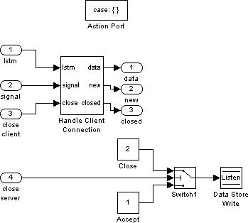
There is a subsystem in this state which handles the connection made by the client
and performs send/receive operations. The close server
input is fed into a Switch block as the switching
input. The parameters of this block is the same as the one mentioned above. If the
server model is stopped, this input becomes 1 which makes the block
to pass the first input, a constant value of 2 which indicates the "Close" state.
In other words, a value of 1 for the switching input causes the program to go to
the "Close" state in which the listening stream is closed. A value of zero for the
switching input indicates that the model is running, hence the program stays in
the same state and continues accepting connections.
The listening stream created by the Stream Listen block in the "Listen" state is passed on to the "Handle Client Connection" subsystem along with the signal (sawtooth wave) to be sent to the client and the constant close client input used to force the client to close the connection. The subsystem returns the data received from the client model along with the new and closed flags which indicate new data received and peer closed respectively. The next figure depicts this subsystem.
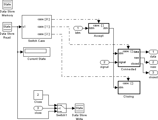
This subsystem is basically the state machine responsible for handling client connections.
The state of this portion of the model is stored in a memory space as a global variable
using a Data Store Memory block with a Data store name of State. The Data Store Read block reads the value of the "State" variable and feeds it into
the Switch Case block. It also feeds its output
to a display for monitoring purposes.
In this subsystem, there are three states available. The first state which is indicated by switch case 0 is the "Accept" state in which client connections are accepted by the server. The listening stream fed into the "Handle Client Connection" subsystem is passed on to this state to be used by the Stream Accept block. The second state is called "Connected" in which one client has connected to the server and sends/received data to/from the server model. This state is indicated by switch case 1. The signal fed into the "Handle Client Connection" subsystem is passed on to this state to be sent to the client model. The third state is the "Closing" state in which the connection stream created in the "Accept" state is closed. Note that these states are each implemented inside a Switch Case Action Subsystem block. The connection stream created inside the "Accept" state subsystem is passed on to the other two states to refer to it.
The output of the Data Store Read which is the "State" variable value is fed as a third input to a Switch block. The switching input of this block is the close input coming from the main diagram which is a constant value of 0. As long as this value is zero, the program stays in the same state (third input is passed by the Switch block). Once the user changes it to 1, the first input which indicates the "Closing" state is passed by the block. Therefore, the user can force the client to close the connection by changing this constant value to 1. The next figure depicts the "Accept" state subsystem.
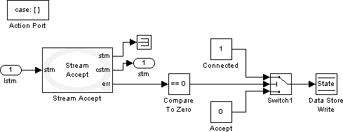
The Stream Accept block uses the non-blocking listening stream to accept new connection. Once a connection is accepted, it creates a connection stream which is passed on to other states to refer to it. For details about this block, you can refer to Stream Accept block reference page. The listening stream is connected to a Terminator sink block since there is no more use for it. Since the Stream Accept block is non-blocking, it returns immediately. Now if a connection is pending while the block is executing, it returns an error output of zero. This output is compared to zero and fed into a Switch block as the switching input. With error output being zero, the block passes the first input which refers to the "Connected" state indicating that the program should switch to the "Connected" state. If the error output is anything but zero (no connection was pending or some error occurred), the Switch block passes the third input to the Data Store Write block referring to the "Accept" state. In other words, in case of errors or no pending connections, the program stays in the same state until a connection is accepted. The next figure illustrates the "Connected" state subsystem.
The Stream Send block writes the data from its data input, which is the signal coming from the main diagram, to the stream send buffer. The Stream Flush block flushes data on the send buffer to the underlying communication channel. The stream is passed by the first Stream block to the next Stream blocks to refer to it. The Stream Receive block receives data from the client model and outputs them from the data output port to the main diagram to be displayed on a scope. The connection stream returned by the Stream Receive block is terminated since there is no more use for it. For more information on the above mentioned blocks, you can refer to Stream Send, Stream Flush and Stream Receive blocks' reference pages.

The Stream Send block writes the data from its data input, which is the signal coming from the main diagram, to the stream send buffer. The Stream Flush block flushes data on the send buffer to the underlying communication channel. The stream is passed by the first Stream block to the next Stream blocks to refer to it. The Stream Receive block receives data from the client model and outputs them from the data output port to the main diagram to be displayed on a scope. The connection stream returned by the Stream Receive block is terminated since there is no more use for it. For more information on the above mentioned blocks, you can refer to Stream Send, Stream Flush and Stream Receive blocks' reference pages.
The Advanced communications blocks would output an error code called -QERR_WOULD_BLOCK
in cases where the block would block if it was using blocking mode. In other words,
since they are non-blocking, they output this error code to indicate that the operation
cannot be performed without blocking which is not considered an error case. The
program should stay in the "Connected" state in these cases. That is the reason
for comparing the error outputs of the Stream blocks to zero in addition to -QERR_WOULD_BLOCK
error code. If you look at the error output of the Stream Send
block for example, it is fed into a Compare to Zero
block which checks if it is less than zero. It is also fed into a Compare to Error block which checks if it is not equal to -QERR_WOULD_BLOCK
error code. For more information about this block, please refer to Compare to Error block reference page.
The outputs of the two comparison blocks are fed into a Logical Operator which performs an AND operation on them. Same implementation
is used for the other two Stream blocks' error outputs. There is only one difference
between the three Compare to Zero blocks and that
is the operator chosen. The outputs of the 3 Logical Operator
blocks performing AND operations are fed into a second Logical Operator performing an OR operation on them. The output of this block
is then passed in to a Switch block as the switching
input. This implementation causes the program to switch to the "Closing" state if
any of the Stream blocks actually encountered an error case (the error output is
less than zero for the first two Stream blocks in the sequence or less than or equal
to zero for the last Stream block in addition to it not being equal to -QERR_WOULD_BLOCK
error code for all the Stream blocks). If there are no errors occurring, the program
stays in the same state to continue handling the accepted connection.
For the Stream Receive block, the error output is further compared to zero to check if it is equal to zero. If it is indeed equal to zero, then the peer has closed the connection and the subsystem returns the closed output to the main diagram to be displayed on a scope. The error output also gets compared to zero to check if it is greater than zero. If it is indeed greater than zero, the block has actually received new data and the subsystem returns the new output to the main diagram to be displayed on a scope. The next figure illustrates the "Closing" state subsystem.
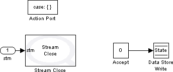
In this state, the connection stream fed into it from the upper level diagram gets closed by the Stream Close block. For details about this block, please refer to Stream Close block reference page. The program is also directed to state number 0 or the "Accept" state to start the process of handling client connections all over again. This concludes the "Handle Client Connection" subsystem explanation. The next figure illustrates the "Close" state from the main diagram.
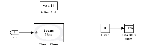
In this state, the listening stream created by the Stream Listen block in the "Listen" state gets closed by the Stream Close block. The program is also directed to state number zero in the main diagram or the "Listen" state to start listening on a specific URI for connections.
Before explaining the details of the "quarc_advanced_nonblocking_client" model, it should be mentioned that with our server implementation, once a client connects to the server, no more clients can connect to it. By default, the new clients attempting to connect would wait some time until the waiting time for the protocol in use gets expired. At this point, they would give a timeout error and exit. You can change this behavior by queuing the waiting clients using the backlog option of URIs.
Client Model
The "quarc_advanced_nonblocking_client" model contains a simple state machine with four states and no nested state machines involved. The next figure illustrates the "quarc_advanced_nonblocking_client" sample model's main diagram.
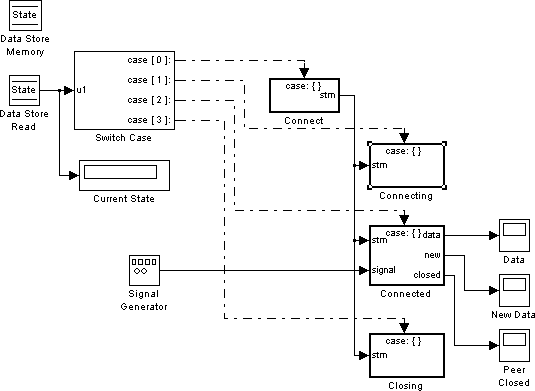
The four states available in the client model are the following; the first state (state 0) is called the "Connect" state in which the client attempts to connect to a local or remote host. The second state (state 1) is called the "Connecting" state in which the program polls the events associated with the connection stream created in the "Connect" state. The model stays in this state until the connection is accepted from the server side. The third state (state 2) is called the "Connected" state responsible for performing send/receive operation with the server. The implementation for this state is identical to the one for the "Connected" state in the server model. The fourth and last state is called the "Closing" state which closes the connection stream upon closing connection or any error occurrence. It also has the same implementation as the "Close" state in the server model's main diagram (related to the main state machine). Note that the connection stream created in the "Connect" state is passed on to the other three states to refer to it. The Signal Generator block generates the square wave which is sent to the server model upon connecting. The next figure illustrates the "Connect" state subsystem.
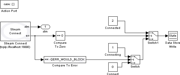
The Stream Connect block connects to a local or remote server using the specified URI in its block parameters dialog. Since we need to connect to the "quarc_advanced_nonblocking_server" server model, we use the same URI here as the one used for that model to listen on. The operating mode should be non-blocking, thus the Non-blocking parameter is enabled in this block's parameters dialog. The connection stream created by this block is passed as an input to other Stream blocks to refer to it. Since the stream is non-blocking, every other Stream block that uses this stream would also be non-blocking. For more information about this block, please refer to the Stream Connect block reference page.
Since the block is in non-blocking mode, it returns immediately. If the connection
has been established, then the err output will be
zero. If the connection is pending then the error code -QERR_WOULD_BLOCK
is returned. If the connection failed then another negative error code is returned.
Therefore, the err output is compared to zero and
then fed into a Switch block as the switching input.
It also gets compared to the error code -QERR_WOULD_BLOCK and then
fed into another Switch block as its switching input.
Now if the error is equal to zero, the Switch block
connected to the compared to zero error, passes the first input which refers to
the "Connected" state. In other words, a zero value for the error means the connection
has been established and the program should go to the state in which sending/receiving
of data take place. If the error is not equal to zero, the Switch block passes the third input which is the output of the second
Switch block. Two situations are possible here;
the error is equal to the -QERR_WOULD_BLOCK error code meaning that
the connection is pending, or the error is not equal to the -QERR_WOULD_BLOCK
error code which means that an actual error occurred. If the first situation arises,
the output of the second Switch block would refer
to the "Connecting" state and forces the program to go to this state to start polling
for connection to be accepted by the server. In the second situation, the output
would refer to the "Connect" state which indicates that there was an error while
trying to connect to the server, hence the program should stay in the "Connect"
state. The next figure illustrates the "Connecting" state subsystem.
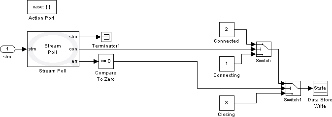
In this state, the client model polls for a connection to be accepted by the server model. The Stream Poll block, in general, polls for events associated with the connection stream passed to it as an input. In our case, it polls for connection to be accepted by the server model. For more information about this block, please refer to the Stream Poll block reference page. In order to force the block to poll for connection to complete or to be accepted, the Wait for connection to complete parameter should be enabled in the block parameters dialog. As a matter of fact, only this parameter is enabled in the parameters dialog for the purpose of this state as shown in the figure below.
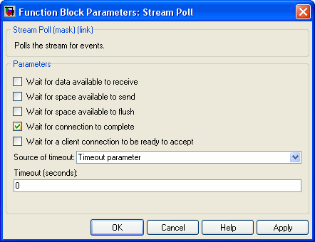
Enabling this parameter enables the conn output port. This output is a boolean value indicating whether a non-blocking Stream Connect block has finished making the connection which suits our situation well. This output is connected to a Switch block as the switching input. If the conn output is true, it means that the connection is established and the Switch block passes the first input referring to the "Connected" state. If, on the other hand, the conn output is false, the connection is still pending and the Switch block passes its third input referring to the same state ("Connecting"). The err output is negative in case of errors. Therefore it gets compared to zero and then fed into a Switch block as the switching input. If the error is negative, an error has occurred and the Switch block passes the third input referring to the "Closing" state. In other words, in case of errors, the program is forced to go to the "Closing" state in which the connection stream is closed. If the error is not negative, then the output of the first mentioned Switch block is passed. Depending on the value of the conn output, the program either stays in the same state until the connection is established or goes to the "Connected" state.
Notice that the connection stream is connected to a Terminator block since there is no more use for it.
As discussed before, the implementation of the "Connected" state subsystem is identical to the "Connected" state subsystem in the "quarc_advanced_nonblocking_server" model, hence not explained here. Same fact is true for the "Closing" state. The only difference between this state and the one in the server model is that the program gets directed to the "Connect" state after closing the connection stream in this model while it gets directed to the "Listen" state after closing the listening stream in the server model.
Once the models are created and built, you could run both models and open the two "Data" scopes to see if the data are received on both ends. The following figures illustrate these scopes for the server and the client model respectively.
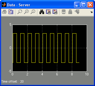
As you can see in the figures, the "Data" scope of the server traces a square wave sent by the client model while the "Data" scope of the client traces a sawtooth wave sent by the server model. This verifies that the models have indeed communicated with each other.
With this implementation for our models, they support the persistent connection feature. The client model tries to establish a connection with the server even if the server has not started yet. It would not give any errors and exit in case the server is not running. It waits forever until the server starts up unless the user manually stops it. The server also listens for connection and tries to accept new connections forever and never exits unless stopped by the user.
The advantage of using non-blocking mode for communications is its suitability for periodic tasks. That is because you can use the Advanced communications blocks in the main diagram without interfering with the sampling time performance. Note however that not all communication protocols support non-blocking mode. Therefore, make sure the protocol in use does support this mode or you have to use blocking mode instead.
 CAUTION: With the non-blocking mode, unlike the blocking mode, you cannot
have models with different sample rates communicating with each other. The reason
is that the non-blocking mode uses the sample rates of models. Consider a client
model with a sampling rate of 1 Hz and a server model with a sampling rate of 1
kHz. The server sends data at a much higher rate than the client could receive,
resulting in data loss. This is not the fact when using the blocking mode where
all the communications are done in asynchronous threads without any sampling rate.
 CAUTION: When using multiple Stream Send
or Stream Receive blocks for one connection in non-blocking
mode, always make sure that the order of blocks receiving/sending data is the same
as the order in which they are connected using the stream being passed by stm input/output ports. To show why this situation is important to take
care of, consider the case where you have two Stream Receive
blocks in sequential order. The first block should read from the stream before
the second block. Since the blocks are non-blocking, the second block may receive
the data meant for the first block before the first block could receive it due to
some latency in the first block's execution. This is undesirable and should be avoided.

Copyright ©2025 Quanser Inc. This page was generated 2025-11-01. Submit feedback to Quanser about this page.
Link to this page.