MATLAB Command Line
Click to copy the following command line to the clipboard. Then paste it in the MATLAB Command Window:
quarc_spi_io_expander_demoQUARC SPI I/O Expander Demo
This is a simple example of using an SPI device with QUARC. It interfaces with an MCP23S17 16-bit digital I/O expander.
It is important to note that with SPI communications there are no signals to indicate whether a read or write is being performed. With SPI communications, data is always read and written at the same time. Hence, every write operation results in the same amount of data being read. Thus, when using the Stream blocks to communicate using SPI, it is important to always perform the write first followed by a read of exactly the same number of bytes. A Stream Write-Read block may be used for this purpose, or separate Stream Write blocks followed by a Stream Read block which reads the same number of bytes as the number of bytes written. The Stream Read will not cause another SPI bus cycle because the data being read will already be in the stream receive buffer.
System Requirements
This demonstration is run using the QUARC for Windows or QUARC for Win64 target with a Quanser QPID or QPIDe data acquisition card for SPI support. This example may also be run on other SPI-capable QUARC targets, such as the QUARC Linux DuoVero Target on the QBot 2 or QBall 2. No QPID(e) card is required in that case. Note that a software license for the desired target is required.
To run on other QUARC targets supporting SPI, the appropriate HIL board will need to be selected, voltage levels will need to be checked (+3.3V required), and the port and frame option of the URI in the Stream Call block will likely need to be changed. Further details may be found below under the heading Running the example on a different target.
This example also requires an MCP23S17 16-bit digital I/O expander from Microchip Technology Inc., wired to SPI port 0 of the target. The example requires the following connections to the MCP23S17 device, if a PDIP, SOIC or SSOP package is used. Do not use these pinouts for the QFN package! Refer to the datasheet for details.
|
Pin |
Name |
Connection |
|---|---|---|
|
1 |
GPB0 |
Wire to pin 21 (GPA0). |
|
2 |
GPB1 |
Wire to pin 22 (GPA1). |
|
3 |
GPB2 |
Wire to pin 23 (GPA2). |
|
4 |
GPB3 |
Wire to pin 24 (GPA3). |
|
5 |
GPB4 |
Wire to pin 25 (GPA4). |
|
6 |
GPB5 |
Wire to pin 26 (GPA5). |
|
7 |
GPB6 |
Wire to pin 27 (GPA6). |
|
8 |
GPB7 |
Wire to pin 28 (GPA7). |
|
9 |
VDD |
Wire to +3.3V. |
|
10 |
VSS |
Wire to ground. |
|
11 |
CS |
Wire to SS of the QPID(e) to use as SPI chip select. |
|
12 |
SCK |
Wire to SPI SCK of the QPID(e) to use a SPI clock. |
|
13 |
SI |
Wire to SPI MOSI of the QPID(e). |
|
14 |
SO |
Wire to SPI MISO of the QPID(e). |
|
15 |
A0 |
Wire to ground (bit 0 of hardware address). |
|
16 |
A1 |
Wire to ground (bit 1 of hardware address). |
|
17 |
A2 |
Wire to ground (bit 2 of hardware address). |
|
18 |
RESET |
Wire to +3.3V. |
| Note that the above table only applies to the PDIP, SOIC and SSOP packages. Do not use these pinouts with the QFN package. |
Wiring the port B digital I/O to the port A digital I/O is only to perform a digital loopback. This example writes a digital sine wave to port B and reads the values at port A.
Configuring the Demonstration
The URI used by the Stream Call block determines the baud rate and other options used for SPI communications. The options have been configured to match those required by the MCP23S17 device and should not be changed. The baud rate, however, may be modified but should never be faster than 10 MHz (10e6) which is the limit for the MCP23S17 device.
To change the URI of the Stream Call block, double-click on the block to open its configuration dialog, as shown below.
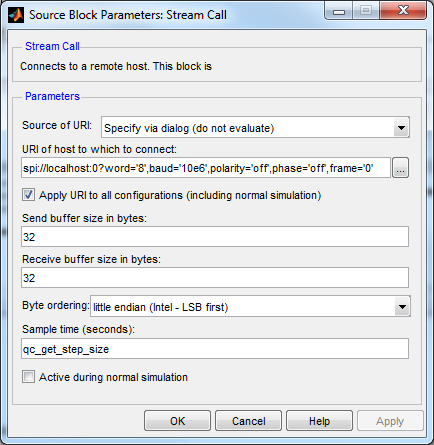
In the URI of host to which to connect field, replace the value of the baud option in the URI with the desired baud rate. If the example is being run on a target other than Windows then the port number and frame option may need to be changed as well. See the SPI Protocol documentation for details on the format of the URI.
Click OK to close the configuration dialog.
Running the Model Using the QUARC Target for Windows
Please note that in order to be able to run this part of the demo, you must have purchased the QUARC Target for Windows as part of your license. In addition you must have satisfied the software and hardware requirements found in the QUARC Installation Guide.
To open the model click on the "Open this model" button found on the top right corner of this page.
Select from the menu of the diagram, or select from the simulation mode combo box on the toolbar.
Select from the menu of the diagram, or press Ctrl+B while the diagram is the active window. A great deal of output will appear in the Diagnostic Viewer about the progress of the build. If you cannot see the Diagnostic Viewer, you can open it by selecting from the menu of the diagram, or clicking on the View Diagnostics hyperlink at the bottom of the diagram. If you have MATLAB R2013b or earlier then the output will appear in the MATLAB Command Window.
If the build is successful, then the line:
*** Created executable quarc_spi_io_expander_demo.rt-win64
will appear in the Diagnostic Viewer. Finally, QUARC will download the model to the QUARC Target for Windows. The line:
### Model quarc_spi_io_expander_demo has been downloaded to target 'shmem://quarc-target:1' (54784 bytes)
will appear in the Diagnostic Viewer indicating that the code was successfully downloaded to the QUARC Target. If any errors occur, appropriate error messages will appear in the Diagnostic Viewer.
Double click on the Input and Output blocks to open the input and output Scopes.
Click on the button or select from the menu of the diagram to connect to the model.
Start the model by clicking on the button or selecting from the menu of the diagram. The item of the menu may also be used to both connect and start the model in one operation.
A sine wave will appear in the Input Scope as shown below. It shows the sine wave being written to port B of the digital I/O expander. Notice that the Scope trace is moving in actual time. In other words, the trace passes the 10 second mark after 10 seconds have passed since in external mode, QUARC runs the model in real-time.
An identical sine wave should appear in the Output Scope as well, as illustrated below:
The identical sine wave appears because port A is wired to port B, so any value written to port B will appear at port A as the input value. Disconnecting one of the wires joining port A to port B will change the output of this Scope because one of the digital lines will no longer be looped back.
Click on the button or select from the menu of the diagram to stop the model. The item of the menu may also be used.
Running the example on a different target
To run the example on a different target, refer to the instructions on the Running QUARC Examples on Remote Targets page.
The URI of the Stream Call block must also be changed to suit the particular target. Below are sample URIs for different QUARC targets that support SPI:
|
Target |
Port |
Chip Select |
URI |
|---|---|---|---|
|
QUARC Windows Target with QPID(e) |
0 |
SS |
spi://localhost:0?word='8',baud='10e6',polarity='off',phase='off',frame='56' |
|
QUARC Win64 Target with QPID(e) |
0 |
SS |
spi://localhost:0?word='8',baud='10e6',polarity='off',phase='off',frame='56' |
|
QUARC Linux DuoVero Target on QBot 2 |
1 |
CS0 |
spi://localhost:1?word='8',baud='10e6',polarity='off',phase='off',frame='0' |
|
QUARC Linux DuoVero Target on QBall 2 |
1 |
CS0 |
spi://localhost:1?word='8',baud='10e6',polarity='off',phase='off',frame='0' |
When wiring the I/O Expander on a different target, use the same wiring but replace the QPIDe with the equivalent I/O on the target platform. The table above shows the SPI port and chip select to use for some sample targets.
Copyright ©2026 Quanser Inc. This page was generated 2026-05-13. Submit feedback to Quanser about this page.
Link to this page.
