
Stream Write-Read
Sends and receives data atomically over a stream. This block is intended for use in the main diagram.
Library
QUARC Targets/Communications/Intermediate MATLAB Command Line Click to copy the following command line to the clipboard. Then paste it in the MATLAB Command Window: qc_open_library('quarc_library/Communications/Intermediate')
Description
The Stream Write-Read block writes data to the stream, flushes the data to the underlying communication channel and then receives data. For protocols that support exclusive access to the communication channel it will also attempt to gain exclusive access to the channel for the combined write-read operation. For example, for the I2C protocol it will perform a combined I2C message in which the write is done first followed by the read. By doing a combined I2C message the bus is not released between the write and the read operation. This exclusivity is important for I2C devices in which the address of a register within the device is often specified in the write operation and the read operation then reads from that register. If a combined message were not used then another I2C device on the bus could intervene between the write and the read operation.
| For protocols which do not support exclusive access to their associated bus, this block cannot perform the write-read operation atomically and will be equivalent to a Stream Write followed by a Stream Read block. |
The operation of this block is affected by the blocking mode of the stream connected to its input. Streams have two modes: blocking (the default) and non-blocking. If a Stream Call or Stream Answer block is used to create the stream, then the stream will be non-blocking. If a Stream Connect or Stream Accept block is used to create the stream then the blocking mode of the stream is determined by the Stream Connect or Stream Listen block.
This block attempts to store all of the data at its data input in the stream buffer. If the stream has been configured to swap bytes due to endian differences then this block will swap the order of the bytes within each element in the input signal when storing the data in the stream buffer. It will also flush the stream each time that it executes. The size of the stream buffer is set by the Send buffer size parameter of the Stream Call or Stream Answer block that created the stream.
This block receives values from the stream after the write is complete. The size and data type of the received data is determined by the Output data type and Dimensions parameters of the block. If the stream has been configured to swap bytes then this block will swap the order of the bytes within each element that it reads before writing them to its data output. Multi-dimensional and bus signals are supported.
Since the Intermediate Stream blocks are non-blocking, this block does not wait. If fewer bytes are available than the size of the output signal then the new output will be zero (false). If all the data requested is available then the new output will be non-zero (true). The err output will be 0, indicating that no errors occurred.
If the connection has been closed gracefully by the peer then it sets cls to a non-zero (true) value and returns zero (false) at its new output once there are fewer bytes left to read than the size of the output signal. Otherwise the cls output is zero and the new output returns true (non-zero). Once there are fewer bytes left in the stream buffer than the size of the output data vector then it sets cls to true to indicate the connection has been closed. A graceful closure of the connection by the peer is not considered an error, so the err output is zero in this case.
If an error occurs, then the block returns a negative error code at its err output. The Compare to Error block may be used to check for specific error codes. If the stream is not valid because it is not yet connected, the err output will be zero since this condition is expected and the validity of the stream may be checked using the con output of the Stream Call or Stream Answer blocks.
This block does not support two threads calling Stream Write-Read at the same time, nor can Stream Write or Stream Read be called at the same time.
Helpful Hints
Other uses of this block
 Although it is intended for use in the main diagram with the other Intermediate
stream blocks, the Stream Write-Read block may be used with the Advanced stream blocks,
even in an asynchronous thread.
Although it is intended for use in the main diagram with the other Intermediate
stream blocks, the Stream Write-Read block may be used with the Advanced stream blocks,
even in an asynchronous thread.
Datagram size and UDP
For packet or message-based protocols in non-blocking mode, the number of bytes
sent over the communication channel in each packet may be larger than the number
of bytes in the input signal, even if the block is configured to minimize latency.
If the data cannot be flushed to the underlying communication channel without blocking
then it remains in the stream buffer and will be written to the underlying communication
channel along with the new data on the next sampling instant. This situation is
typically recognized when a QERR_DATAGRAM_TOO_LARGE error is returned
at the peer when trying to receive the data.
The number of bytes in each packet may be as large as the stream buffer size unless the underlying protocol restricts the maximum packet size. For example, the bufsize option of the UDP protocol has a default value of 1492 bytes. Hence, up to 1492/8 = 186 doubles may appear in a single datagram at the peer if the stream buffer is more than 1492 bytes in size. To restrict the size of the datagrams sent, either reduce the stream buffer size or set the bufsize option of the UDP URI. Reducing the stream buffer size may cause new data to be discarded if there is not enough room in the stream buffer, but it limits the number of datagrams sent. Setting the bufsize option of the UDP URI causes the stream API to send multiple datagrams, if necessary, to flush the stream buffer. A typical URI would be "udp://localhost:18000?bufsize=512", which sets the maximum datagram size to 512 bytes (64 doubles).
An even better solution is to allow the datagrams to be large and instead receive the full datagram at the peer. For example, if the stream buffer size and maximum datagram size are both 1492 bytes, then attempt to receive 1492 bytes at the peer (or 187 doubles). For the Simulink blocks or stream API functions, that means using a stream buffer that is at least 1492 bytes in length at the peer. For the lower-level communications API, specify a buffer of at least 1492 bytes in the call to qcomm_receive.
Variable-size signals
When using the Stream Write-Read block with variable-size signals in subsystems, make sure any
Action Port
MATLAB Command Line
Click to copy the following command line to the clipboard. Then paste it in the MATLAB Command Window:
doc ActionPort;,
Enable
MATLAB Command Line
Click to copy the following command line to the clipboard. Then paste it in the MATLAB Command Window:
doc Enable or
Trigger
MATLAB Command Line
Click to copy the following command line to the clipboard. Then paste it in the MATLAB Command Window:
doc Trigger ports are
configured to propagate the sizes of variable-size signals during execution. See
Variable-Size Signals
for more information on variable-size signals.
Input Ports
stm
A reference to the stream created by the Stream Call or Stream Answer block. If these blocks have not established a connection the err output of the Stream Write-Read block will be zero.
data
The data to write to the stream. The input signal is treated as an atomic unit.
It will never write part of the data to the stream. These semantics make it much
easier to deal with streams in Simulink where it is difficult to deal with "parts"
of a signal. Note that the buffer size for the stream must be at least as large
as the input signal or -QERR_STREAM_BUFFER_TOO_SMALL is returned
by the err output. Multi-dimensional and variable-size signals as well as bus inputs are supported.
See Using Bus Objects with QUARC
for more information on bus signals, and refer to Variable-Size Signals
for more details on variable-size signals.
Output Ports
stm
A reference to the stream. This output is merely a copy of the stm input. Providing this output makes it much easier to establish the execution order of Stream blocks in the diagram because Simulink generally executes daisy-chained blocks in sequence.
data
The data read from the stream buffer. The output signal is treated as an atomic
unit. It will never read part of the data from the stream buffer. These semantics
make it much easier to deal with streams in Simulink where it is difficult to deal
with "parts" of a signal. Note that the buffer size for the stream must be at least
as large as the output data or -QERR_STREAM_BUFFER_TOO_SMALL
is returned by the err output. Multi-dimensional and variable-size
signals, as well as bus signals are supported. See
Using Bus Objects with QUARC
for more information on bus signals.
new
Indicates whether the value(s) presented at the data port represent newly received data from the peer. If this output is zero (false) then no data has been received from the peer in this sampling instant.
cls
Indicates whether the connection has been closed by the peer. This output is non-zero (true) when the remote host gracefully closes the connection. Otherwise it is zero (false).
sent
A Boolean value indicating whether the input signal was written to the stream buffer successfully. This value will be true (non-zero) if the data was written successfully and zero otherwise. If the data could not be written immediately without blocking then this output will be zero. This output merely indicates that the data was written to the stream buffer. It does not validate that the data was sent to the underlying communication channel or delivered to the remote peer successfully.
peer
A Boolean value indicating whether an error has occurred due to the peer not yet being designated. For a UDP server, the client is generally unknown until the first receive operation has been completed successfully, because the UDP protocol is a connection-less protocol. Not knowing the peer means no data will be sent. However, it is not regarded as a fatal error because the stream does not need to be closed in this case. It merely indicates that no client has "connected" yet by sending a datagram to the server. The UDP server should continue listening on the port and attempting to receive data. This output can be used to determine why no data has been sent (see the sent port) when there are no other errors and the operation should not have blocked.
err
An int32 value indicating whether any errors occurred. It is zero if no errors
occurred and a negative error code otherwise. See Error Codes
for the different error codes and their values. Use the
Compare to Error
block rather than the error code itself to check for specific
error codes. To check for errors in general, simply test whether the output is non-zero.
Note that the QERR_NO_DESIGNATED_PEER error is not reported at this output.
It is signalled at the peer output instead since it is
not regarded as a fatal error requiring closure of the stream. The QERR_WOULD_BLOCK
error is also not reported at this output because it simply indicates that the data
could not be sent without blocking. The sent output may
be used to determine whether the data was actually written to the stream buffer.
Data Type Support
The Stream Write-Read block accepts signals of any of the built-in Simulink data types at its data input, including multi-dimensional signals. Fixed point is not currently supported.
Variable-size signals are accepted at its data input. In this case, it uses the current dimensions of the signal to determine how many elements to write. Variable-size signals may be multi-dimensional, but cannot be bus signals. See Variable-Size Signals for more information on variable-size signals.
The Stream Write-Read block also accepts bus signals at its data input. Buses are useful for sending a mix of different data types in a single write operation. Bus signals are created using the Bus Creator MATLAB Command Line Click to copy the following command line to the clipboard. Then paste it in the MATLAB Command Window: doc('Bus Creator') block supplied with Simulink. A Simulink.Bus MATLAB Command Line Click to copy the following command line to the clipboard. Then paste it in the MATLAB Command Window: doc('Simulink.Bus') object must be created that defines the data types of the signals within the bus. This object may be created using the Bus Editor and then saved to a MAT file. To ensure that the bus object is always defined, load this MAT file within the InitFcn callback of the Simulink model. See Using Bus Objects with QUARC for more information on bus signals.
Parameters and Dialog Box
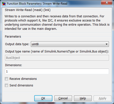
Output data type
The data type of the data output. This parameter
determines the data type of the elements that are read from the stream. If this
parameter is set to Inherited via back propagation then the data type
of the output is determined by the block connected to the data
output.
If this field is set to Specify via dialog then the Output type name
parameter is used to define the data type of the output. Refer to the Output type name
parameter for details.
Output type name
This parameter should be the name of a variable in the MATLAB workspace that defines the
data type of the output. This variable may be a Simulink.AliasType, Simulink.NumericType,
Simulink.StructType or Simulink.Bus object. Simulink.Bus objects may be
created using the Simulink Bus Editor, available from the menu of the
Simulink diagram.
|
Set the Dimensions field to |
Dimensions
The dimensions of the output data. This parameter determines how
many elements are read from the stream and the dimensions of the data
at the data output of the block. It may be a vector
with each element being at least 1. For example, to specify a 3-vector,
specify 3 as the Dimensions parameter.
To output a 2x3 matrix, enter
[2, 3]
.
This field should be 1 when using a bus output.
For variable-sized signals, this parameter specifies the maximum dimensions of the output signal. The dimensions should match the maximum dimensions of the signal on the peer side.
Receive dimensions
This option is used with variable-sized signals. Checking this option causes the current dimensions of the output signal to be read from the stream prior to the data itself. The output signal is then sized according to the received dimensions. The block automatically determines the type of integer required for each dimension based on the maximum dimensions of the output signal specified in the Dimensions parameter. For example, if the maximum size of a dimension is less than 256 then a single 8-bit integer is received for that dimension. If the maximum size is less than 65536 then a 16-bit integer is used. Dimensions larger than 32-bits are not supported. Refer to Variable-Size Signals for more information on variable-size signals.
Send dimensions
This option is used with variable-sized signals. Checking this option causes the current dimensions of the input signal to be sent prior to the data itself so that the peer knows the dimensions of the signal. The block automatically determines the appropriate integer size required for each dimension based on the maximum dimensions of the input signal. For example, if the maximum size of a dimension is less than 256 then a single 8-bit integer is used to transmit that dimension. If the maximum size is less than 65536 then a 16-bit integer is used. Dimensions larger than 32-bits are not supported. Refer to Variable-Size Signals for more information on variable-size signals.
Targets
|
Target Name |
Compatible* |
Model Referencing |
Comments |
|---|---|---|---|
|
Yes |
Yes |
||
|
Yes |
Yes |
||
|
Yes |
Yes |
||
|
Yes |
Yes |
||
|
Yes |
Yes |
||
|
Yes |
Yes |
||
|
Yes |
Yes |
||
|
Yes |
Yes |
||
|
Yes |
Yes |
||
|
Yes |
Yes |
||
|
Yes |
Yes |
||
|
Yes |
Yes |
||
|
Yes |
Yes |
||
|
Yes |
Yes |
Last fully supported in QUARC 2018. |
|
|
Rapid Simulation (RSIM) Target |
Yes |
Yes |
|
|
S-Function Target |
No |
N/A |
Old technology. Use model referencing instead. |
|
Normal simulation |
Yes |
Yes |
If the Stream Call or Stream Answer block which created the stream is not active during normal simulation, then the Stream Write-Read block does nothing. Otherwise it writes the data to the stream. |
See Also
Copyright ©2026 Quanser Inc. This page was generated 2026-05-13. Submit feedback to Quanser about this page.
Link to this page.
