MATLAB Command Line
Click to copy the following command line to the clipboard. Then paste it in the MATLAB Command Window:
quarc_spi_multiple_devices_demoQUARC SPI Multiple Devices Demo
This is an example of using multiple SPI devices with QUARC connected to the same SPI port. It interfaces to a LCD display and a digital I/O expander. Separate chip selects are used to access each device. This example makes extensive use of the Stream Write-Read block in order to simplify the model, since SPI operations always write and read at the same time due to the nature of the SPI bus.
System Requirements
This demonstration is run using the QUARC for Windows or QUARC for Win64 target with a Quanser QPID or QPIDe data acquisition card. This example may also be run on other SPI-capable QUARC targets, such as the QUARC Linux DuoVero Target on the QBot 2 or QBall 2. No QPID(e) card is required in that case. Note that a software license for the desired target is required.
To run on other QUARC targets supporting SPI, the appropriate HIL board will need to be selected, voltage levels will need to be checked (+3.3V required), and the port and frame option of the URI in the Stream Call block will likely need to be changed. Further details may be found below under the heading Running the example on a different target.
This example also requires an NHD-C12832A1Z-FSW-FBW-3V3 COG (Chip-On-Glass) Liquid Crystal Display Module from Newhaven Display International Inc., wired to SPI port 0 of the target. The example requires the following connections to the LCD module. Refer to the -->datasheet for details.
|
|
| Do not power the backlight (A) using a QPIDe digital I/O pin. The backlight voltage cannot exceed +3.0V and the QPIDe digital I/O are +3.3V. Furthermore, the QPIDe digital I/O do not have the drive strength required to power the LCD backlight. |
The VDD power (as opposed to the backlight) should be provided by a separate isolated +3.3V supply. Be sure to connect the ground of the supply to DGND. If a +3.3V supply is not available, then the QPIDe DIO2 pin may be used. However, this solution is not recommended as the overall current capability of a bank of digital outputs is limited.
For information on programming the LCD module via the SPI interface, refer to the Sitronix ST7565R datasheet.
Furthermore, this example requires an MCP23S17 16-bit digital I/O expander from Microchip Technology Inc., that is also wired to SPI port 0 of the target. The example requires the following connections to the MCP23S17 device, if a PDIP, SOIC or SSOP package is used. Do not use these pinouts for the QFN package! Refer to the datasheet for details. Note that digital output 55 of the QUARC target hardware should be connected to the chip select of the I/O expander rather than digital output 56 (SS), which is used for the LCD module.
|
Pin |
Name |
Connection |
|---|---|---|
|
1 |
GPB0 |
Wire to pin 21 (GPA0). |
|
2 |
GPB1 |
Wire to pin 22 (GPA1). |
|
3 |
GPB2 |
Wire to pin 23 (GPA2). |
|
4 |
GPB3 |
Wire to pin 24 (GPA3). |
|
5 |
GPB4 |
Wire to pin 25 (GPA4). |
|
6 |
GPB5 |
Wire to pin 26 (GPA5). |
|
7 |
GPB6 |
Wire to pin 27 (GPA6). |
|
8 |
GPB7 |
Wire to pin 28 (GPA7). |
|
9 |
VDD |
Wire to +3.3V. |
|
10 |
VSS |
Wire to ground. |
|
11 |
CS |
Wire to the QPIDe DIO55 pin to use it as SPI chip select. |
|
12 |
SCK |
Wire to the QPIDe SPI SCK pin. |
|
13 |
SI |
Wire to the QPIDe SPI MOSI pin. |
|
14 |
SO |
Wire to the QPIDe SPI MISO pin. |
|
15 |
A0 |
Wire to ground (bit 0 of hardware address). |
|
16 |
A1 |
Wire to ground (bit 1 of hardware address). |
|
17 |
A2 |
Wire to ground (bit 2 of hardware address). |
|
18 |
RESET |
Wire to +3.3V. |
| Note that the above table only applies to the PDIP, SOIC and SSOP packages. Do not use these pinouts with the QFN package. |
Wiring the port B digital I/O to the port A digital I/O is only to perform a digital loopback. This example writes a digital sine wave to port B and reads the values at port A.
Configuring the Demonstration
Open the QUARC Preferences dialog by selecting from the menu of one of the Simulink diagrams.
The slave option of the URI used by the Stream Call block in the LCD Module subsystem must match the digital output connected to the CS line of the LCD module. If this pin is connected to a different digital output than digital output 56 (SS), then the value of the slave option will need to be changed to match the digital output used. Do not use the same digital output as the one used for the digital I/O expander! The baud rate may also be changed, but the other options should be left alone, because they match the SPI phase and polarity to that required by the LCD module. The LCD module does not support a baud rate faster than 20 MHz (20e6).
To change the URI of the Stream Call block, double-click on the block to open its configuration dialog, as shown below.
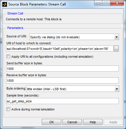
In the URI of host to which to connect field, replace the value of the baud option in the URI with the desired baud rate, or the slave option with the appropriate digital output.
Click OK to close the configuration dialog.
Likewise, the URI used by the Stream Call block in the I/O Expander subsystem determines the baud rate and other options used for SPI communications with the I/O expander. The options have been configured to match those required by the MCP23S17 device and should not be changed. The baud rate, however, may be modified but should never be faster than 10 MHz (10e6) which is the limit for the MCP23S17 device. If digital output 55 is not used as the chip select for the I/O expander, then this option should be changed to match the digital output driving the chip select of the I/O expander. Do not use the same digital output as the one used for the LCD module!
To change the URI of the Stream Call block, double-click on the block to open its configuration dialog, as shown below.
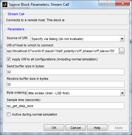
In the URI of host to which to connect field, replace the value of the baud option in the URI with the desired baud rate, or the frame option with the appropriate digital output.
Click OK to close the configuration dialog.
Running the Model Using the QUARC Target for Windows
Please note that in order to be able to run this part of the demo, you must have purchased the QUARC Target for Windows as part of your license. In addition you must have satisfied the software and hardware requirements found in the QUARC Installation Guide.
To open the model click on the "Open this model" button found on the top right corner of this page.
Select from the menu of the diagram, or select from the simulation mode combo box on the toolbar.
Select from the menu of the diagram, or press Ctrl+B while the diagram is the active window. A great deal of output will appear in the Diagnostic Viewer about the progress of the build. If you cannot see the Diagnostic Viewer, you can open it by selecting from the menu of the diagram, or clicking on the View Diagnostics hyperlink at the bottom of the diagram. If you have MATLAB R2013b or earlier then the output will appear in the MATLAB Command Window.
If the build is successful, then the line:
*** Created executable quarc_spi_multiple_devices_demo.rt-linux_duovero
will appear in the Diagnostic Viewer. Finally, QUARC will download the model automatically to the QUARC Target for Windows. The line:
### Model quarc_spi_multiple_devices_demo has been downloaded to target 'shmem://quarc-target:1' (443904 bytes)
will appear in the Diagnostic Viewer indicating that the code was successfully downloaded to the QUARC Target. Please note that QUARC supports building and downloading code to remote targets, however in this example the QUARC Target is local, and hence the code is downloaded to local shared memory. If any errors occur, appropriate error messages will appear in the Diagnostic Viewer.
Double click on the Input and Output blocks to open their Scopes.
Click on the button or select from the menu of the diagram to connect to the model.
Start the model by clicking on the button or selecting from the menu of the diagram. The item of the menu may also be used to both connect and start the model in one operation.
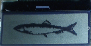
An image of a fish will appear on the LCD display as depicted below:
Double-click on the Select image or animation Manual Switch to set it in the downward position (toward the animation branch). A stick man will walk across the LCD display. See the video to see what it looks like.
A sine wave will also appear in the Input Scope as shown below. It shows the sine wave being written to port B of the digital I/O expander. Notice that the Scope trace is moving in actual time. In other words, the trace passes the 10 second mark after 10 seconds have passed since in external mode, QUARC runs the model in real-time.
An identical sine wave should appear in the Output Scope as well, as illustrated below:
The identical sine wave appears because port A is wired to port B, so any value written to port B will appear at port A as the input value. Disconnecting one of the wires joining port A to port B will change the output of this Scope because one of the digital lines will no longer be looped back.
The model is able to communicate with both devices over the same SPI port because they employ two different chip select lines. A separate Stream Call block is used to open the same SPI port for each device. The frame option in the URI (or slave option) identifies the chip select to use in each case so that the two streams do not conflict with one another.
Click on the button or select from the menu of the diagram to stop the model. The item of the menu may also be used.
Running the example on a different target
To run the example on a different target, refer to the instructions on the Running QUARC Examples on Remote Targets page. Minor changes will also need to be made for the LCD Module and I/O expander:
LCD Module
The HIL Initialize block parameters should be modified
to use a card supported on the given target. For example, for the QBot 2, the qbot2 driver should be selected. For
the QBall 2, the qball2 card should be chosen. The following settings on the Digital Outputs tab should also
be configured. Note that the HIL Initialize block saves the settings configured for every card so settings are not
lost when changing cards.
|
Field |
Value |
|---|---|
|
Digital output channels |
[0:2] |
|
Initial digital outputs |
[0 0 1] |
|
Final digital outputs |
[0] |
The URI of the Stream Call block in the LCD Module subsystem must also be changed to suit the particular target. Below are sample URIs for different QUARC targets that support SPI:
|
Target |
Port |
Chip Select |
URI |
|---|---|---|---|
|
QUARC Windows Target with QPID(e) |
0 |
SS |
spi://localhost:0?word='8',baud='10e6',polarity='on',phase='on',slave='56' |
|
QUARC Win64 Target with QPID(e) |
0 |
SS |
spi://localhost:0?word='8',baud='10e6',polarity='on',phase='on',slave='56' |
|
QUARC Linux DuoVero Target on QBot 2 |
1 |
CS0 |
spi://localhost:1?word='8',baud='10e6',polarity='on',phase='on',slave='0' |
|
QUARC Linux DuoVero Target on QBall 2 |
1 |
CS0 |
spi://localhost:1?word='8',baud='10e6',polarity='on',phase='on',slave='0' |
When wiring the LCD module on a different target, use the same wiring diagram but replace the QPIDe with the equivalent I/O on the target platform. The table above shows the SPI port and chip select to use for some sample targets.
I/O Expander
The URI of the Stream Call block in the I/O Expander subsystem must also be changed to suit the particular target. Below are sample URIs for different QUARC targets that support SPI:
|
Target |
Port |
Chip Select |
URI |
|---|---|---|---|
|
QUARC Windows Target with QPID(e) |
0 |
DIO55 |
spi://localhost:0?word='8',baud='10e6',polarity='off',phase='off',frame='55' |
|
QUARC Win64 Target with QPID(e) |
0 |
DIO55 |
spi://localhost:0?word='8',baud='10e6',polarity='off',phase='off',frame='55' |
|
QUARC Linux DuoVero Target on QBot 2 |
1 |
CS1 |
spi://localhost:1?word='8',baud='10e6',polarity='off',phase='off',frame='1' |
|
QUARC Linux DuoVero Target on QBall 2 |
1 |
CS1 |
spi://localhost:1?word='8',baud='10e6',polarity='off',phase='off',frame='1' |
When wiring the I/O Expander on a different target, use the same wiring diagram but replace the QPIDe with the equivalent I/O on the target platform. The table above shows the SPI port and chip select to use for some sample targets. Note the different chip select from the LCD module.
Copyright ©2026 Quanser Inc. This page was generated 2026-05-13. Submit feedback to Quanser about this page.
Link to this page.
