
Ranging Sensor
Measures distance using a ranging sensor such as a time-of-flight sensor or LIDAR.
Library
QUARC Targets/Devices/Third-Party/Sensors MATLAB Command Line Click to copy the following command line to the clipboard. Then paste it in the MATLAB Command Window: qc_open_library('quarc_library/Devices/Third-Party/Sensors')
Description
The Ranging Sensor block measures distance using a ranging sensor such as the VL53L1 time-of-flight sensor or RPLIDAR. Note that the VL53L0 time-of-flight sensor is used on the Bitcraze Flow breakout board.
The Ranging Sensor block outputs the measured distance(s), the standard-deviation of the distance measurement(s), the heading(s), and an indication of the quality of the measurement(s). It also produces an output that indicates when a new measurement has been taken, since the block does not wait for the measurement to be generated, but polls the sensor.
Not all ranging sensors support all these outputs. For example, a 1D time-of-flight sensor does not support a heading. In this case, the heading will be zero. For some sensors, such as a LIDAR, the outputs may be vectors representing one complete 360 degree scan of the environment.
For LIDAR, the dist, sigma, head and quality outputs are typically vectors. In this case, each element represents one measurement within a scan of the environment. LIDAR typically perform a 360 degree scan of the environment, so the headings will contain angles from 0 to 360 degrees (in radians). The distance output at the corresponding element represents the distance to an object detected at that heading. The distance and heading are typically plotted on a polar plot, using the Polar Figure block.
If a measurement cannot be taken because an object is too far away, for instance, then the distance measurement and corresponding quality will be zero.
For LIDAR, there are three types of output that may be selected via the Output mode parameter. In Fixed-size output mode, the number of elements in the output vectors will equal the length specified in the Samples per revolution parameter. If this length is less than the number of samples produced by the LIDAR, then the extra samples are simply discarded. If it is more than the number of samples produced by the LIDAR then the remaining elements will not be set. An extra # output is provided containing the number of samples that were actually measured. Note that each scan of a LIDAR may contain a different number of samples.
When the Output mode parameter is set to Variable-size output then the outputs become variable-size signals whose length reflects the number of samples taken by the LIDAR in one complete scan of the environment. The output will be the same as the Fixed-size output case except that invalid samples at the end of the vectors have been removed because the outputs are variable-size.
In the previous two cases, the outputs will contain the LIDAR measurements for one complete scan of the environment. However, the LIDAR may produce heading measurements which vary, even when the same number of samples have been taken. For example, the first measurement may occur at a heading of 0.1 radians at one sampling instant, and at 0.14 radians at another sampling instant. This variation in the headings is a characteristic of the LIDAR, but can make it inconvenient to use the LIDAR measurements.
To remedy this situation so that known headings are always output by the block, the Output mode parameter may be set to Fixed-size interpolated output. In this case, the headings are the same every sampling instant and the distances at those headings are interpolated from the actual LIDAR measurements. For example, if the Samples per revolution parameter is set to 360, then there will be 360 elements in the output vectors and the headings will correspond to 0, 1, 2, 3, ... 359 degrees (expressed in radians). Hence, the number of "samples" will always be the same and the headings will not change. This makes the data much easier to work with.
| Not all sensors support the Fixed-size interpolated output Output mode. Currently the Leishen Lidar does not support the Fixed-size interpolated output Output mode. |
To understand how interpolation works, consider two consecutive measurements from the LIDAR: (r1, theta1) and (r2, theta2). If the desired angle, theta, is between theta1 and theta2, then the computed distance r will be interpolated between r1 and r2 based on the ratio of (theta - theta1) to (theta2 - theta1). A difficulty arises however if r1 and r2 are quite different. For example, suppose (r1, theta1) is detected from the corner of a desk, while (r2, theta2) is measuring a wall behind the desk. In this case, interpolation may not make sense because it may look like there is a line going from the corner of the desk to the wall behind it.
To resolve this issue, the block has a Maximum distance for interpolation parameter. If the difference between r1 and r2 is greater than this distance, then interpolation is not performed. Instead, the closest LIDAR measurement is used without interpolation. If the Maximum distance for interpolation parameter is set to inf then all measurements are interpolated. If it is set to zero, then no measurements are interpolated. The default value is 5 cm (0.050 m).
Another issue that can arise is that some LIDARs can occasionally miss samples so that theta2 - theta1 is larger than expected. In this case, it also may not make sense to do interpolation because there is too large a span in which no samples have been collected. Hence, there is also a Maximum angle for interpolation parameter which causes the distance and quality to be set to zero if theta2 - theta1 exceeds the threshold. To always interpolate, set this parameter to Inf. Do not set it to a value smaller than the distance between consecutive LIDAR measurements or else all the output will be zero. The default value is 5 degrees.
Each type of sensor generally requires different parameter values for optimal operation. Suitable parameters for different types of sensors are as follows:
|
Sensor |
Ranging Distance |
Samples per Revolution |
Timing Budget |
Measurement Period |
Sample Time |
|---|---|---|---|---|---|
|
VL53L0X time-of-flight |
Long |
- |
0.033 |
0.040 |
1/30 |
|
VL53L1 time-of-flight |
Long |
- |
0.033 |
0.040 |
1/30 |
|
RPLIDAR A1 LIDAR |
Long |
1500 |
- |
- |
1/15 |
|
RPLIDAR A2 M8 LIDAR |
Long |
500 |
- |
- |
1/21 |
|
RPLIDAR A2 M12 LIDAR |
Long |
1000 |
- |
- |
1/21 |
|
RPLIDAR A3 LIDAR |
Long |
1000 |
- |
- |
1/21 |
|
RPLIDAR C1 LIDAR |
Long |
500 |
- |
- |
1/10 |
|
RPLIDAR S2 LIDAR |
Long |
2000 |
- |
- |
1/21 |
|
YDLIDAR LIDAR |
Long |
1500 |
- |
- |
1/100 |
|
Leishen MS10 LIDAR |
Long |
1008 |
- |
- |
1/12 |
|
Leishen M10P LIDAR |
Long |
2000 |
- |
- |
1/15 |
Helpful Hints
LIDAR Specifications
 Do not confuse the samples per second specification of a LIDAR with the number of samples per revolution. For example, the RPLIDAR A2 LIDAR
collects 8000 measurements per second. However, it spins at about 16 revolutions per second. Hence, the number of samples per revolution
is about 8000 [samples/second] / 16 [revolutions/second] = 500 samples per revolution. Hence, the output of the Ranging Sensor block will be
about 500 samples because the block outputs one complete 360 degree scan of the environment i.e., the samples from one revolution. In this
case, the block will produce new outputs about 16 times per second.
Do not confuse the samples per second specification of a LIDAR with the number of samples per revolution. For example, the RPLIDAR A2 LIDAR
collects 8000 measurements per second. However, it spins at about 16 revolutions per second. Hence, the number of samples per revolution
is about 8000 [samples/second] / 16 [revolutions/second] = 500 samples per revolution. Hence, the output of the Ranging Sensor block will be
about 500 samples because the block outputs one complete 360 degree scan of the environment i.e., the samples from one revolution. In this
case, the block will produce new outputs about 16 times per second.
Installation Requirements
Leishen MS10 LIDAR
 When using the Leishen MS10 LIDAR with an LSLIDAR USB-to-serial adapter board, a driver for the Silicon Labs CP210x USB to UART bridge
will need to be installed on some platforms. A suitable driver may be found at
https://www.silabs.com/developers/usb-to-uart-bridge-vcp-drivers?tab=downloads.
When using the Leishen MS10 LIDAR with an LSLIDAR USB-to-serial adapter board, a driver for the Silicon Labs CP210x USB to UART bridge
will need to be installed on some platforms. A suitable driver may be found at
https://www.silabs.com/developers/usb-to-uart-bridge-vcp-drivers?tab=downloads.
Input Ports
This block has no input ports.
Output Ports
dist (m)
The measured distance(s) in metres.
sigma
The estimated standard deviation of the measured distance(s). This output may not be supported by all sensors. In that case, it may be estimated from other information provided by the sensor or will be zero.
head (rad)
The heading(s) in radians. Not all sensors support a heading measurement. In that case, this output will be zero. Heading angles inrease in the positive direction. If 0 is north, then π/2 is east, π is south and 3π/2 is west.
quality (1)
An indication of the quality of the measurement(s). This output will vary between zero and one, with one being the highest quality measurement. For sensors which do not provide quality information, this output will be a binary output - either zero or one, depending on whether the measurement was taken successfully.
new
Indicates whether the data at the outputs is new. Since the block does not wait for the measurement to be taken (since such measurements are often slow compared to typical controller sample rates), this output may be used to determine when a new measurement has been taken. If the measurement is not new, the other outputs will hold their prior values.
#
Indicates the number of elements in the other outputs that are actually valid. This output is only present when the Output mode is set to Fixed-size output.
mdl
An optional uint16 scalar output that indicates the model of the sensor. It is only present if the Output version information parameter is checked.
hw
An optional uint16 4-vector output that provides the hardware version number in the form: [major, minor, release, build]. It is only present if the Output version information parameter is checked.
fw
An optional uint16 4-vector output that provides the firmware version number in the form: [major, minor, release, build]. It is only present if the Output version information parameter is checked.
Data Type Support
This block supports outputs of type double, except for model and version information which is uint16.
Parameters and Dialog Box
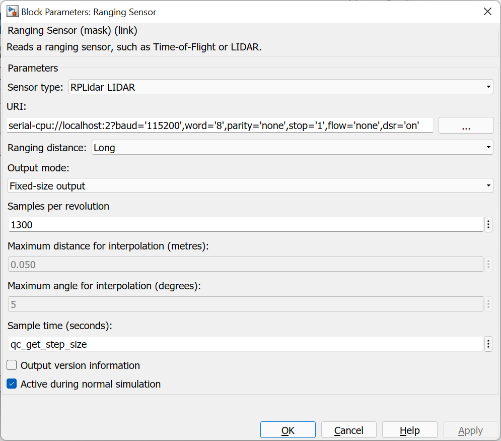
Sensor type
Determines the type of ranging sensor to read. Only the sensors in the list are supported. The URI parameter determines how the block communicates with the selected sensor.
URI
The URI identifying the communication protocol and associated parameters to use to communicate with the ranging sensor. For example, serial://localhost:1?baud=115200 connects to the sensor through serial port 1 (e.g. COM1 or /dev/ttyS1) at 115200 baud. Refer to Universal Resource Identifiers for more information about URIs and the communications protocols supported by QUARC.
On the QCar, for example, a suitable URI for the RPLIDAR A2 M8 is serial-cpu://localhost:2?baud='115200',word='8',parity='none',stop='1',flow='none',dsr='on'. The dsr='on' option allows the DTR and RTS signals to be manually controlled, which is required for the RPLidar sensor because the RTS line is used to control the LIDAR's motor.
The following table lists suitable URIs for various ranging sensors on different platforms:
|
Target(s) |
Sensor |
URI |
|---|---|---|
|
QCar 2 |
RPLIDAR S2 LIDAR |
serial-cpu://localhost:1?baud='1000000',word='8',parity='none',stop='1',flow='none',dsr='on' |
|
QCar 2 |
RPLIDAR A3 LIDAR |
serial-cpu://localhost:1?baud='256000',word='8',parity='none',stop='1',flow='none',dsr='on' |
|
QCar 2 |
RPLIDAR A2 M12 LIDAR |
serial-cpu://localhost:1?baud='256000',word='8',parity='none',stop='1',flow='none',dsr='on' |
|
QCar 2 |
RPLIDAR C1 LIDAR |
serial-cpu://localhost:1?baud='460800',word='8',parity='none',stop='1',flow='none',dsr='on' |
|
QCar |
RPLIDAR A2 M8 LIDAR |
serial-cpu://localhost:2?baud='115200',word='8',parity='none',stop='1',flow='none',dsr='on' |
|
QCar |
Leishen MS10 LIDAR |
serial://localhost:2?baud='460800',word='8',parity='none',stop='1',flow='none' |
|
QBot Platform |
Leishen M10P LIDAR |
serial://localhost:0?baud='512000',word='8',parity='none',stop='1',flow='none',device='/dev/lidar' |
|
Windows |
YDLIDAR LIDAR |
serial://localhost:5?baud='128000',word='8',parity='none',stop='1',flow='none',dsr='on' (when the LIDAR is on COM5) |
|
QDrone 2 |
VL53L0 or VL53L1 time-of-flight |
i2c://localhost:0?address='0x29',baud='400000',memsize='255' |
Ranging distance (tunable offline)
The ranging distance parameter is used to optimize the sensor settings for a particular range of distances. For each sensor, the corresponding ranges will differ. For example, for the VL53L1X Time-of-Flight sensor, the distance ranges for a 100 ms timing budget are:
|
Ranging Distance |
Maximum distance in dark (cm) |
Maximum distance under strong ambient light (cm) |
|---|---|---|
|
Short |
136 |
135 |
|
Medium |
290 |
76 |
|
Long |
360 |
73 |
Timing budget (tunable offline)
This parameter is used for the time-of-flight sensors. It determines the amount of time budgeted for reading the reflected light. For the VL53L0X and VL53L1X sensors, 20 ms is the minimum timing budget and may only be used for the short ranging distance. A budget of 33 ms works for all ranging distances, and a budget of 140 ms allows the maximum distance to be reached in long distance mode. Increasing the timing budget increases the maximum distance the device can measure and improves repeatability. However, average power consumption increases accordingly. The maximum timing budget is 1000 ms for these sensors.
Measurement Period (tunable offline)
The measurement period is used for the time-of-flight sensors and determines the amount of time between measurements. For the VL53L0X and VL53L1X sensors, the measurement period must be at least 4 ms longer than the timing budget. The measurements are done in a background thread, so the sample time of the block is not affected by the measurement period. However, the output of the block will not be updated any faster than the measurement period, even if the sample time is faster.
Output mode
The output mode determines the nature of the block's outputs when a LIDAR sensor is selected. Since LIDAR typically scans its environment and produces multiple measurements for each 360 degree scan, the outputs are generally vectors instead of scalars. The output mode determines the nature of these outputs.
When the Fixed-size output option is selected, the outputs are fixed-size vectors whose length is determined by the Samples per revolution parameter. Since LIDAR does not always produce the same number of samples per revolution, however, not all of the elements in these outputs will be valid measurements. An additional # output is generated in this mode so that the number of valid measurements in the output is known. Note that a "valid" measurement simply indicates that the LIDAR produced a sample. The sample may indicate that the distance could not be measured at that heading, in which case the corresponding quality element will be zero, but the sample is still considered "valid".
If this parameter is set to Variable-size output then rather than provide a # output indicating the number of valid samples, instead the outputs are variable-size and their current length will reflect the number of valid samples acquired at that sampling instant.
Finally, if this parameter is set to Fixed-size interpolated output then the output vectors are fixed-size, but all the elements are always valid because the data is interpolated from the actual LIDAR data to produce the requested number of samples per revolution. In this mode the data is easiest to work with because the headings are always the same. If the Samples per revolution parameter is N, then the headings will be 0, 1/N, 2/N, ..., (N-1)/N. The corresponding distances will be interpolated from the actual LIDAR measurements.
Samples per revolution
The number of LIDAR samples to output per complete scan. This parameter determines the length of the output vectors. In the case of variable-size outputs, it determines the maximum length of the output vectors. Note that this is not the same as the number of samples per second. LIDARs like the RPLIDAR A2 LIDAR perform 8000 measurements per second, but the LIDAR spins at about 16 revolutions per second, so one 360 degree scan consists of about 500 samples.
Maximum distance for interpolation (metres) (tunable online)
This parameter is only used when the Output mode is set to Fixed-size interpolated output. If the difference in the distances r1 and r2 between two consecutive LIDAR samples (r1, theta1) and (r2, theta2) is less than this parameter then the corresponding output element(s) will be interpolated from the two samples. If the distance is greater than this parameter then the distance corresponding to the closest angle will be used.
Setting this parameter to zero causes the distance corresponding to the closest angle to always be used. Setting it to inf causes linear interpolation to always be used.
Maximum angle for interpolation (degrees) (tunable online)
This parameter is only used when the Output mode is set to Fixed-size interpolated output. If the difference in the angles theta1 and theta2 between two consecutive LIDAR samples (r1, theta1) and (r2, theta2) is less than this parameter then the corresponding output element(s) will be interpolated from the two samples. If the difference is greater than this parameter then the distance and quality will be set to zero for the samples in that span.
Setting this parameter to inf causes linear interpolation to always be used. Setting it to a value less than the angle between any two consecutive LIDAR samples will result in the distances and quality always being zero, so this is not recommended.
Sample time (second)
The sampling period (in seconds) at which the sensor data are output from the Ranging Sensor block. A sample time of 0 indicates that the block will be treated as a continuous time block. A positive sample time indicates that the block is a discrete time block with the given sample time.
A sample time of -1 indicates that the block inherits its sample time. Since this is a source block, only inherent the sample time when it is placed in a conditionally executed subsystem, like a Triggered or Enabled Subsystem, or in a referenced model.
The default sample time is set to qc_get_step_size, which is a QUARC function that returns the fundamental sampling time of the model. Hence, the default sample time is a discrete sample time with the same sampling time as the fixed step size of the model.
Output version information
If this option is checked then the block will have three extra outputs: mdl, hw and fw for the sensor model, hardware version and firmware version respectively.
Active during normal simulation
If this option is checked then the block will attempt to read from the sensor in normal simulation. In this case, the sensor must be connected to the host PC rather than the target.
Targets
|
Target Name |
Compatible* |
Model Referencing |
Comments |
|---|---|---|---|
|
Yes |
Yes |
||
|
Yes |
Yes |
||
|
Yes |
Yes |
||
|
Yes |
Yes |
||
|
Yes |
Yes |
||
|
Yes |
Yes |
||
|
Yes |
Yes |
||
|
Yes |
Yes |
||
|
Yes |
Yes |
||
|
Yes |
Yes |
||
|
Yes |
Yes |
||
|
Yes |
Yes |
||
|
Yes |
Yes |
||
|
Yes |
Yes |
Last fully supported in QUARC 2018. |
|
|
Rapid Simulation (RSIM) Target |
Yes |
Yes |
|
|
S-Function Target |
No |
N/A |
Old technology. Use model referencing instead. |
|
Normal simulation |
Yes |
Yes |
Copyright ©2026 Quanser Inc. This page was generated 2026-05-13. Submit feedback to Quanser about this page.
Link to this page.
