
Serial Receiver Write
Emulates commands from a serial receiver such as DSMX or S.BUS. This block is intended for use in the main diagram.
Library
QUARC Targets/Communications/Serial Receiver MATLAB Command Line Click to copy the following command line to the clipboard. Then paste it in the MATLAB Command Window: qc_open_library('quarc_library/Communications/Serial Receiver')
Description
The Serial Receiver Write block emulates commands from a serial receiver over a stream. The stream is typically a serial connection. The commands for up to 16 channels are packed into frames and transmitted over the stream, along with any extra information specific to the protocol selected. A vector is also input indicating which channel data is new, as some protocols do not send all the channel data in one frame.
This block does not wait for data to be transmitted. It is non-blocking since frames are transmitted over the stream in a background thread. The most recent commands are transmitted by the block. It acts as a server while the Serial Receiver Read block acts as a client.
The Serial Receiver Write block maintains a persistent connection with the stream, so it will reconnect automatically if the connection is lost. The current state of the connection is also output from the block.
If an error occurs, then the block returns a negative error code at its err output. The Compare to Error block may be used to check for specific error codes.
Configuration Requirements
DSM serial configuration
 The serial stream for DSMX or DSM2 is typically configured for 115200 baud, one stop bit, no parity
and no flow control. The URI to use is:
The serial stream for DSMX or DSM2 is typically configured for 115200 baud, one stop bit, no parity
and no flow control. The URI to use is:
serial://localhost:0?baud='115200',parity='none',stop='1',flow='none'.
Note that the port number in the URI must be changed to match the UART used to receive the DSMX or DSM2 signals.
S.BUS serial configuration
The serial stream for S.BUS must be configured for 100000 baud, two stop bits, even parity
and no flow control. The URI to use is:
serial://localhost:0?baud='100000',parity='even',stop='2',flow='none'.
Note that the port number in the URI must be changed to match the UART used to receive the S.BUS signals.
S.BUS signal inversion
S.BUS signals are generally inverted from the signals produced by a standard UART, so
an inverter may be required on the S.BUS signal prior to the UART. For serial ports which support
polarity inversion, the polarity=on option can be added
to the URI to do the polarity inversion so that an external logic inverter is not required. For example:
serial://localhost:0?baud='100000',parity='even',stop='2',flow='none',polarity='on'
Input Ports
ch
This input depends on the Gain, Offset parameters. This input is always a 16 element vector where each element corresponds to a separate RC channel. However the range changes depending on aforementioned parameters. Refer to the parameters for more details.
valid
A 16-element vector indicating whether the values presented at the ch input port are valid. If an element is false (zero) then no data for the corresponding channel will be written to the peer in this sampling instant.
This input is a vector because protocols like DSMX or DSM2 require more than one frame to be sent to provide 16 channels worth of data. Note, however, that the block will automatically send multiple frames if more channels are valid than the number of channels that fit in a frame.
fade
The number of missed frames for the DSM protocols, as a uint16.
phase
A 16-bit boolean vector of the phases for each channel for the DSM protocols, as a boolean vector.
Note that 22ms DSM2 does not support phases, but 11ms DSM2 and all speeds of DSMX do.
flg
The flags for the S.BUS frame, as a uint8.
Output Ports
state
The current status of the connection. The possible states are tabulated below:
|
State |
Name |
Description |
|---|---|---|
|
0 |
SERIAL_RECEIVER_STATE_NOT_CONNECTED |
The stream is not connected. |
|
1 |
SERIAL_RECEIVER_STATE_CLOSING |
The stream is closing the connection to the peer. |
|
2 |
SERIAL_RECEIVER_STATE_CONNECTING |
The stream is listening for new connections. |
|
3 |
SERIAL_RECEIVER_STATE_CONNECTED |
The stream is connected to the peer. |
err
If an error occurs sending the data, then this output is a negative QUARC error code indicating the cause of the problem. Otherwise it is zero. It is a 32-bit signed integer.
Parameters and Dialog Box
Main Pane
The Main pane of the dialog appears as follows:
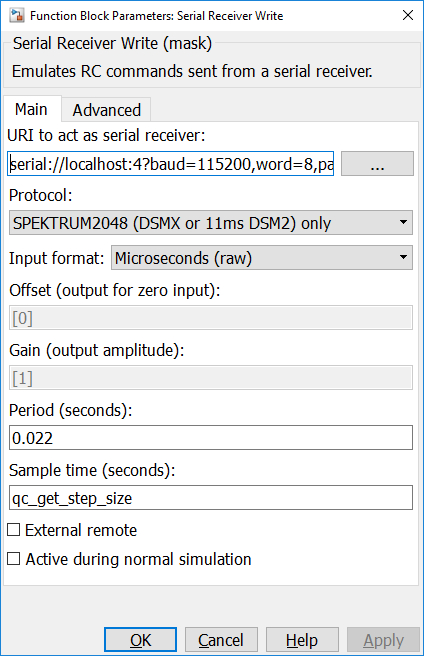
URI to act as a serial receiver
The URI on which to listen for client connections. The URI typically refers to a serial port to which the device expecting a receiver is connected. See the configuration options above for settings appropriate for each protocol.
Protocol
Indicates which protocol to use.
Input format (tunable online)
This parameter sets the Offset and Gain parameters to values which map common input formats to the range of values for the RC channels. The table below describes the different input formats:
|
Format |
Description |
|---|---|
|
Bipolar percentage |
Maps an input range of [-1,1] to the typical [1000,2000] range such that -1 becomes 1000, 0 becomes 1500 and 1 becomes 2000. For protocols which only support a 1024 range, it maps the input range to [500,1000]. Any values outside this range are mapped according to the same affine transformation. This input format is useful when the channels represent -100% to 100% throttle. |
|
Unipolar percentage |
Maps an input range of [0,1] to the typical [1000,2000] range such that 0 becomes 1000 and 1 becomes 2000. For protocols which only support a 1024 range, it maps the input range to [500,1000]. Any values outside this range are mapped according to the same affine transformation. This input format is useful when the channels represent 0 to 100% throttle. |
|
Seconds |
Maps the input range of [0.001,0.002] to the typical [1000,2000] range such that 0.001 becomes 1000 and 0.002 becomes 2000 so that the input is the RC pulse width in seconds. For protocols which only support a 1024 range, it maps the input range to [500,1000]. Any values outside this range are mapped according to the same affine transformation. This input format is useful when the channels are being used to drive PWM pulse widths via the HIL blocks. |
|
Microseconds (raw) |
The input is the raw RC value, which is the RC pulse width in microseconds. For protocols which only support a 1024 range, it divides the raw RC value by two to map it to the [500,1000] range instead of [1000,2000]. |
|
Custom |
The custom input format allows a custom offset and gain to be specified for each input channel using the Offset and Gain parameters. |
Offset (tunable online)
The offsets to apply to the input signals to convert to the available range per channel. The gain is applied first and then the offset. This parameter is used when the Input format is set to Custom. The parameter may be a scalar or vector value, with up to 16 elements. If the value contains less than 16 elements then the last element is applied to the remaining channels. Hence, a scalar value will apply to all channels.
Gain (tunable online)
The gains to apply to the input signals to convert to the available range per channel. The gain is applied first and then the offset. This parameter is used when the Input format is set to Custom. The parameter may be a scalar or vector value, with up to 16 elements. If the value contains less than 16 elements then the last element is applied to the remaining channels. Hence, a scalar value will apply to all channels.
Period (tunable offline)
The period at which to send frames. The period should generally match the protocol being used. For DSM protocols, the period should either be 22 ms (0.022) or 11 ms (0.011). For the S.BUS protcol, the period should be 7 ms (0.007).
The period is independent of the sample time of the block. Only the most recent inputs to the block will be used every time this period expires. If more valid channel data is provided than will fit in one frame then multiple periods may be used by the block to transmit all the channel data.
Synchronization byte(s) (tunable online)
Determines the synchronization value(s) used to detect the start of an S.BUS frame. This value is typically 0x0f in hexadecimal (or 15 decimal) or 0xf0 in hexadecimal (or 240 decimal).
This parameter is only visible when an S.BUS protocol is selected.
External remote (tunable offline)
Indicates whether the receiver is an internal or external remote, since the DSM protocol varies slightly when an external remote is used.
This parameter is only visible when a DSM protocol is selected.
Advanced Pane
The Advanced pane of the dialog appears as follows:
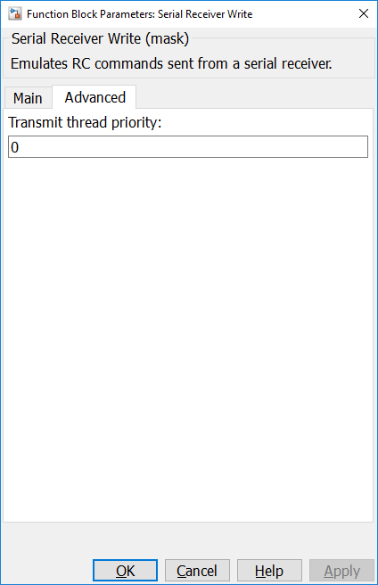
Transmit thread priority (tunable offline)
The priority of the transmit thread that is used to write frames emulating a serial receiver. Higher priority values indicate higher priority. A priority of zero is the lowest priority.
Targets
|
Target Name |
Compatible* |
Model Referencing |
Comments |
|---|---|---|---|
|
Yes |
Yes |
||
|
Yes |
Yes |
||
|
Yes |
Yes |
||
|
Yes |
Yes |
||
|
Yes |
Yes |
||
|
Yes |
Yes |
||
|
Yes |
Yes |
||
|
Yes |
Yes |
||
|
Yes |
Yes |
||
|
Yes |
Yes |
||
|
Yes |
Yes |
||
|
Yes |
Yes |
||
|
Yes |
Yes |
||
|
Yes |
Yes |
Last fully supported in QUARC 2018. |
|
|
Rapid Simulation (RSIM) Target |
Yes |
Yes |
|
|
S-Function Target |
No |
N/A |
Old technology. Use model referencing instead. |
|
Normal simulation |
Yes |
Yes |
See Also
Copyright ©2026 Quanser Inc. This page was generated 2026-05-13. Submit feedback to Quanser about this page.
Link to this page.