
VAL Read Sensors
Reads a combination of input channels of a vehicle.
Library
QUARC Targets/Vehicles/Basic MATLAB Command Line Click to copy the following command line to the clipboard. Then paste it in the MATLAB Command Window: qc_open_library('quarc_library/Vehicles/Basic')
Description
The VAL Read Sensors block reads the specified channels every time the block is executed. This block can read more than one type of channel at the same time. The number and types of channels available depends on the vehicle selected in the corresponding VAL Initialize block.
Input Ports
This block has no input ports.
Output Ports
The number of output ports depends on the Vector outputs parameter. If this option is checked then there is one output port for each type of channel specified. Each of these outputs is a vector containing the measurements read from the channels specified in the corresponding Channels parameter. The first output port will be for the analog channels, if used, the next port will be for the encoder channels, if used, etc.
Otherwise there is one output port for each channel and each port outputs the measurement read from the corresponding channel. The first set of output ports will be for the analog channels, if used, the next set of output ports will be for the encoder channels, if used, etc. Refer to the documentation on the Vector output parameter below for more details.
Each type of sensor input is specified by a Channels parameter, indicating which channels are being read. This parameter is a vector of channel numbers. Each element of the vector should be entered as an integer number between 0 and one less than the number of channels supported by the vehicle (see vehicle documentation for a list of supported sensors and corresponding channel numbers). For example,
[0 5 6]
denotes channels 0, 5 and 6. Channel numbers need not be consecutive. Nor do they need to be specified in ascending order. Sensor data read from a vehicle will appear in the same order as the channels in the vector.
Data Type Support
The VAL Read Sensors block outputs signals of type double
for the analog and other channels, it outputs signals of type int32
or double for the encoder channels
and it outputs any of the built-in Simulink datatypes except fixed point for the
digital channels. See the Signal Data Types pane below for information on
how the output data type is determined.
Parameters and Dialog Box
Individual Panes
Main Pane
The Main pane of the dialog appears as follows:
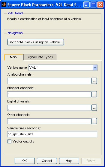
Vehicle Name
The name of the vehicle whose analog channels will be read. Vehicles are configured using the VAL Initialize block. Place a VAL Initialize block in your diagram to add a vehicle name to the list.
Analog channels
The analog channels to read. The number of analog channels available depends on the vehicle selected. The output is the voltages read from the analog inputs.
Encoder channels
The encoder channels to read. The number of channels available depends on the vehicle selected. The output is the count values read from the encoder counters.
Digital channels
The digital channels to read. The number of channels available depends on the vehicle selected. The output is the states read from the digital inputs.
Other channels
The other channels to read. The number of channels available depends on the vehicle selected. The output is the values read from the other inputs.
Sample time
The sample time of the block. A sample time of 0 indicates that the block will be treated as a continuous time block. A positive sample time indicates that the block is a discrete time block with the given sample time.
A sample time of -1 indicates that the block inherits its sample time. Since this is a source block, only inherent the sample time when it is placed in a conditionally executed subsystem, like a Triggered or Enabled Subsystem, or in a referenced model.
The default sample time is set to qc_get_step_size, which is a QUARC function that returns the fundamental sampling time of the model. Hence, the default sample time is a discrete sample time with the same sampling time as the fixed step size of the model.
Vector outputs
If this option is checked then the block will have a vector output for each type of channel specified with one element in the vector for each channel of that type. The values read from each channel will appear in the vector in the same order as the channels in the corresponding Channels parameter. For example, if analog channels 3 and 4 are selected, then the first output port will be a 2-vector with the first element containing the voltages read from analog input 3 and the second element containing the voltages read from analog input 4. Each output port will be labeled with the prefix indicating the type of channel represented by that output port. Refer to the table below for an explanation of the prefixes used.
If this option is not checked then the block will have one output for each channel. The output ports will appear in the same order as the channels in the corresponding Channels parameter. Each port will be labeled with a prefix indicating the channel type and the corresponding channel number.The prefixes are:
|
|
|
|---|---|
|
|
analog |
|
|
encoder |
|
|
digital |
|
|
other |
Signal Data Types Pane
The Signal Data Types pane of the dialog appears as follows:
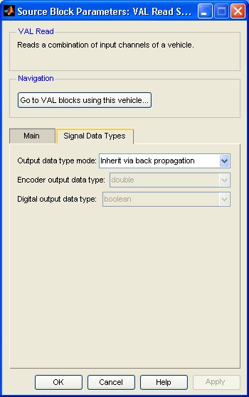
Output data type mode
Sets the data type of the output to be inherited by back propagation or to be specified
explicitly in the dialog. This parameter only affects the encoder and digital channels.
The analog and other channels are always double.
If back propagation is selected then the data type of the encoder and digital outputs
will be determined by the blocks to which these outputs are connected. If an encoder
output is not connected or it is connected to a block which supports multiple datatypes,
then the output data type will be double. If a digital
output is not connected or it is connected to a block which supports multiple datatypes,
then the output data type will be boolean.
Otherwise the data type of the encoder outputs can be specified explicitly using the Encoder output data type parameter and the data type of the digital outputs can be specified explicitly using the Digital output data type parameter.
Encoder output data type
Sets the data type of the encoder outputs explicitly.
Digital output data type
Sets the data type of the digital outputs explicitly.
Targets
|
Target Name |
Compatible* |
Model Referencing |
Comments |
|---|---|---|---|
|
Yes |
Yes |
||
|
Yes |
Yes |
||
|
Yes |
Yes |
||
|
Yes |
Yes |
||
|
Yes |
Yes |
||
|
Yes |
Yes |
||
|
Yes |
Yes |
||
|
Yes |
Yes |
||
|
Yes |
Yes |
||
|
Yes |
Yes |
||
|
Yes |
Yes |
Fully supported. |
|
|
Yes |
Yes |
||
|
Yes |
Yes |
Fully supported. |
|
|
No |
No |
Not supported. |
|
|
Rapid Simulation (RSIM) Target |
No |
No |
|
|
S-Function Target |
No |
N/A |
Old technology. Use model referencing instead. |
|
Normal simulation |
Yes |
Yes |
Fully supported. |
Copyright ©2026 Quanser Inc. This page was generated 2026-05-13. Submit feedback to Quanser about this page.
Link to this page.