
Video3D Capture
Captures video images from a 3D imaging device, such as an RGBD camera.
Library
QUARC Targets/Multimedia MATLAB Command Line Click to copy the following command line to the clipboard. Then paste it in the MATLAB Command Window: qc_open_library('quarc_library/Multimedia')
Description
The Video3D Capture block grabs video images from a 3D imaging device, such as an RGBD camera and outputs each frame as a colour, grayscale or depth image. The Video3D Capture block must be used in conjunction with a Video3D Initialize block, which configures the 3D image device. For information about the cameras supported on particular devices, follow the link to the corresponding device on the QUARC Data Acquisition Card Support page.
The block supports a variety of image streams, including RGB, infrared and depth streams. The output may be selected as a MATLAB RGB (HxWx3) image, a MATLAB grayscale (HxW) image, or a depth image (HxW) with units of metres. It also supports fisheye, gyroscope, accelerometer and 6-DOF pose streams when the cameras support it.
The MATLAB RGB image is a three-dimensional matrix representing the red, green and blue components of each pixel in the image. The output dimensions are HxWx3, where H is the height of the image and W is the width of the image.
The MATLAB grayscale image is a two-dimensional matrix representing the luminance of each pixel in the image. The output dimensions are HxW, where H is the height of the image and W is the width of the image. A grayscale image takes less memory and is faster to process.
The depth image is a two-dimensional matrix representing the distance in metres from the camera to each pixel in the image. The output dimensions are HxW, where H is the height of the image and W is the width of the image.
For gyroscope and accelerometer streams, the output is a 3-vector of (x,y,z) coordinates. Note that the coordinates are in the Quanser Standard Axes.
For the 6-DOF pose stream, the output is a 21-vector whose elements are defined as follows. Note that the coordinates are in the Quanser Standard Axes.
|
Element Index |
Description |
|---|---|
|
1 |
Translation in X |
|
2 |
Translation in Y |
|
3 |
Translation in Z |
|
4 |
Linear velocity in X |
|
5 |
Linear velocity in Y |
|
6 |
Linear velocity in Z |
|
7 |
Linear acceleration in X |
|
8 |
Linear acceleration in Y |
|
9 |
Linear acceleration in Z |
|
10 |
Rotation as a quaternion (W [scalar] component) |
|
11 |
Rotation as a quaternion (X component) |
|
12 |
Rotation as a quaternion (Y component) |
|
13 |
Rotation as a quaternion (Z component) |
|
14 |
Angular velocity about X |
|
15 |
Angular velocity about Y |
|
16 |
Angular velocity about Z |
|
17 |
Angular acceleration about X |
|
18 |
Angular acceleration about Y |
|
19 |
Angular acceleration about Z |
|
20 |
Tracker confidence as a fraction (0 to 1) |
|
21 |
Mapper confidence as a fraction (0 to 1) |
A variety of different output data types are supported that are compatible with The MathWorks' Computer Vision System Toolbox MATLAB Command Line Click to copy the following command line to the clipboard. Then paste it in the MATLAB Command Window: doc vision;, including both integer and floating-point data types.
Other parameters allow various camera settings to be tuned to accomodate the environment. Note however that not all cameras support tuning all available settings. In that case, the camera settings are simply ignored and no error is generated.
More than one Video3D Capture block may be used at the same time. For example, the RGB image from an RGBD camera and the depth image from the same camera may be streamed at the same time using two Video3D Capture blocks. Some cameras, such as the Intel RealSense R200 camera, allow streaming from the RGB, left and right infrared streams and depth stream simultaneously.
 For cameras like the Intel T265 with two fisheye lenses, it may be necessary to have two Video3D Capture blocks and
to read both streams at the same time.
For cameras like the Intel T265 with two fisheye lenses, it may be necessary to have two Video3D Capture blocks and
to read both streams at the same time.
Since more than one Video3D Capture block may be used at the same time, and some of the streams share common settings, such as the infrared and depth streams, some parameters should only be set in one instance of the block. For example, when using both the infrared and depth streams of an Intel RealSense R200 camera, the Video3D Capture blocks for the left and right infrared streams should have the white balance set to Do not set white balance, the exposure set to Do not set exposure and the laser emitter set to Do not set laser emitter. Then in the Video3D Capture block for the depth stream, set the white balance, exposure and laser emitter to the desired settings.
If more than one block changes these settings then it would become confusing because the last block to execute would determine the actual settings applied. For the settings with an "Override" option, leaving the box unchecked is equivalent to not setting that parameter.
Typically, stereoscopic RGBD cameras like the Intel RealSense R200 camera use the infrared cameras for their depth determination, so the infrared and depth streams share camera settings. The RGB camera, on the other hand, has its own settings. However, since each camera is different, some experimentation is typically required to determine what settings apply to which image streams and which settings are shared between streams.
When a camera has more than one instance of the same type of stream, such as two infrared cameras, the cameras are distinguished using the Stream index parameter. This parameter is typically 0 and 1 for two instances, or 1 and 2. Some experimentation may be required to determine which combination works.
The Video3D Capture block is also capable of outputing the camera intrinsics and the distortion model. To do so, check the Output camera intrinsics and distortion model parameter.The camera intrinsics matrix is a 3x3 matrix containing the focal lengths and principal point, as well as any skew. It takes the form:
|
Fx |
s |
x0 |
|
0 |
Fy |
y0 |
|
0 |
0 |
1 |
where Fx and Fy are the focal length in pixels in the x and y directions respectively, x0 and y0 are the principal point offsets in pixels, and s is the axis skew. For all the cameras currently supported, the axis skew is zero. The x-direction corresponds to columns measured from the left-edge of the image and the y-direction corresponds to rows measured from the top edge of the image.
The distortion model identifies the lens distortion model for the camera. It is an enumerated type which can be displayed in a Display MATLAB Command Line Click to copy the following command line to the clipboard. Then paste it in the MATLAB Command Window: qc_open_library('Display') block.
The distortion coefficients are output as a 5-element vector, although all the coefficients may not be used depending on the distortion model.
If the Output depth scale parameter is checked then an additional output is provided for the depth scale factor. Multiply by this factor to convert the output image to a depth in meters. If depth is output as an RGB image, it converts from the luminance value to meters. Note that this scale factor is generally not needed because the Video3D Capture block already has a very efficient option for outputting the depth data directly in meters, but the scale factor can be useful if initial processing on the depth data as an integral data type is preferred.
Helpful Hints
Video Formats
Cameras typically only support certain resolutions and frame rates. If the Video3D Capture block reports that the
video format is not supported, try other resolutions and frame rates. Typical resolutions are 320x240, 640x480,
1280x720 and 1920x1080, and typical frame rates are 30, 60 and 90 frames per second. For fisheye cameras, a
typical resolution is 880x800. Use the query (<<) button when the target is
powered on to select from a list of stream types, streams, resolutions and frame rates on the target.
Input Ports
brt
The brightness as a fraction between 0.0 and 1.0. This input is only present if the Brightness Override parameter is set to Override using input port.
con
The contrast as a fraction between 0.0 and 1.0. This input is only present if the Contrast Override parameter is set to Override using input port.
hue
The hue as a fraction between 0.0 and 1.0. This input is only present if the Hue Override parameter is set to Override using input port.
sat
The saturation as a fraction between 0.0 and 1.0. This input is only present if the Saturation Override parameter is set to Override using input port.
shp
The sharpness as a fraction between 0.0 and 1.0. This input is only present if the Sharpness Override parameter is set to Override using input port.
gam
The gamma as a fraction between 0.0 and 1.0. This input is only present if the Gamma Override parameter is set to Override using input port.
gain
The gain as a fraction between 0.0 and 1.0. This input is only present if the Gain Override parameter is set to Override using input port.
wbl
The white balance as a fraction between 0.0 and 1.0. This input is only present if the White Balance Override parameter is set to White balance via input port.
bck
The backlight compensation as a fraction between 0.0 and 1.0. This input is only present if the Backlight Compensation Override parameter is set to Override using input port.
exp
The exposure as a fraction between 0.0 and 1.0. This input is only present if the Exposure Override parameter is set to Exposure via input port.
Output Ports
image
When the Output format is set to MATLAB RGB this output is a three-dimensional HxWx3 matrix where H is the image height and W is the image width. It contains the red, green and blue components for each pixel in the image.
When the Output format is set to MATLAB Greyscale this output is a two-dimensional HxW matrix where H is the image height and W is the image width. It contains the shade of grey for each pixel in the image.
When the Output format is set to Distance in metres this output is a two-dimensional HxW matrix where H is the image height and W is the image width. It contains the distance in metres from the camera to each pixel in the image.
The data type depends on the Output data type parameter. The matrix is compatible with The MathWorks' Computer Vision System Toolbox MATLAB Command Line Click to copy the following command line to the clipboard. Then paste it in the MATLAB Command Window: doc vision;.
#
The frame number for the current frame. The data type is a 64-bit unsigned integer (uint64_T). To plot this signal, convert it to a double using a Data Type Conversion MATLAB Command Line Click to copy the following command line to the clipboard. Then paste it in the MATLAB Command Window: qc_open_library('Data Type Conversion') block.
time
The timestamp assigned by the camera to the current frame.
new
This output is true whenever a new frame is being output at the image port. Otherwise it is false.
intrin
A 3x3 single-precision matrix representing the camera intrinsics, namely the focal lengths and principal point offsets in pixels and any axis skew. See the description above for details.
model
An enumerated type describing the lens distortion model for the camera.
coefficients
A five-element single-precision vector of the coefficients for the distortion model. Not all distortion models use all the coefficients. If the coefficients are all zero then it means the output image is already rectified and no distortion model need by applied.
scale
The depth scale factor as a single-precision scalar. The scale factor converts from the image data type to meters.
Parameters and Dialog Box
Main Pane
The Main pane of the dialog appears as follows:
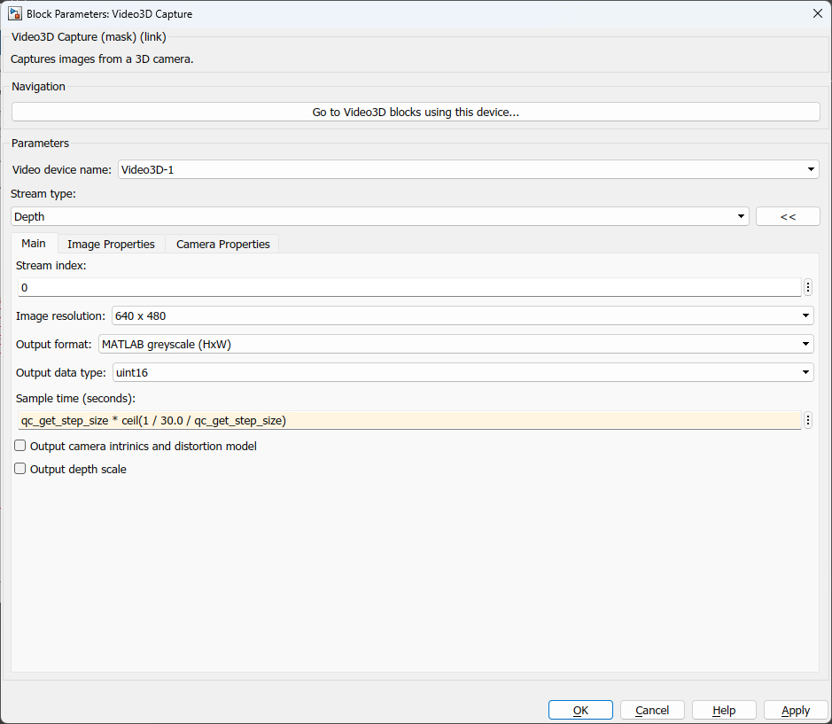
The Main tab contains the core settings affecting the output of the block, such as the image resolution and output format.
Video device name
The identity of the associated Video3D Initialize block. The Video3D Capture block must be associated with a Video3D Initialize block. This parameter will show a list of all the Video3D Initialize blocks in the diagram or "unassigned".
Stream type
The type of image stream to capture from the device. The RGB (red-green-blue) image stream is provided by the color camera on the device. The depth stream provides information about the distance between the camera and objects in the scene. The infrared stream supplies images from the infrared camera on the device. Stereoscopic cameras like the Intel RealSense R200 have more than one infrared stream available from left and right infrared cameras. The fisheye stream provides an image stream from a fisheye camera, for those devices that support it. When there is more than one image stream of the same type, use the Stream index parameter to select individual streams. The gyroscope and accelerometer streams are for cameras that have an inertial measurement unit (IMU). The pose stream is for tracking cameras that track 6-DOF pose information.
Use the query (<<) button beside the stream type field when the target is powered up to connect to the target and get a list of stream types, streams, resolutions and frame rates from which to select the desired settings.
Stream index (tunable offline)
The stream index is used to select between multiple image streams of the same type. It represents a zero-based index of the stream. For example, the Intel RealSense R200 camera has two infrared cameras: a left and a right camera. To access the infrared cameras, set the Stream type to Infrared and then enter 0 as the stream index for the first camera and 1 as the stream index for the second camera.
Image resolution
The resolution of the video images to retrieve. A typical resolution is 640 x 480.
Output format
The format of the output image. The output format may be MATLAB RGB, in which the img output is a three-dimensional HxWx3 matrix, or MATLAB Greyscale, in which the img output is a two-dimensional HxW matrix, or Distance in metres for depth images, in which case the img output is also a two-dimensions HxW matrix.
Output data type
The data type to use for the img output. Both integral and floating-point data types are supported. The output data types are compatible with The MathWorks' Computer Vision System Toolbox MATLAB Command Line Click to copy the following command line to the clipboard. Then paste it in the MATLAB Command Window: doc vision;.
Sample time
The sampling period (in seconds) of the Video3D Capture block. The sample time determines the frame rate. A sample time of 0 indicates that the block will be treated as a continuous time block. A positive sample time indicates that the block is a discrete time block with the given sample time. The sample time cannot be inherited.
The default sample time is set to qc_get_step_size * ceil(0.033 / qc_get_step_size). The qc_get_step_size function is a QUARC function that returns the fundamental sampling time of the model. Hence, the default sample time is a discrete sample time which is a multiple of the fixed step size of the model and close to 1/30 of a second.
Output camera intrinsics and distortion model
Check this option to provide outputs for the camera intrinsics and the distortion model, as well as the distortion coefficients. This will add three additional output ports to the block.
Output depth scale
Check this option to provide an output for the depth scale factor to convert from the given output data type to meters.
Image Properties Pane
The Image Properties pane of the dialog appears as follows:
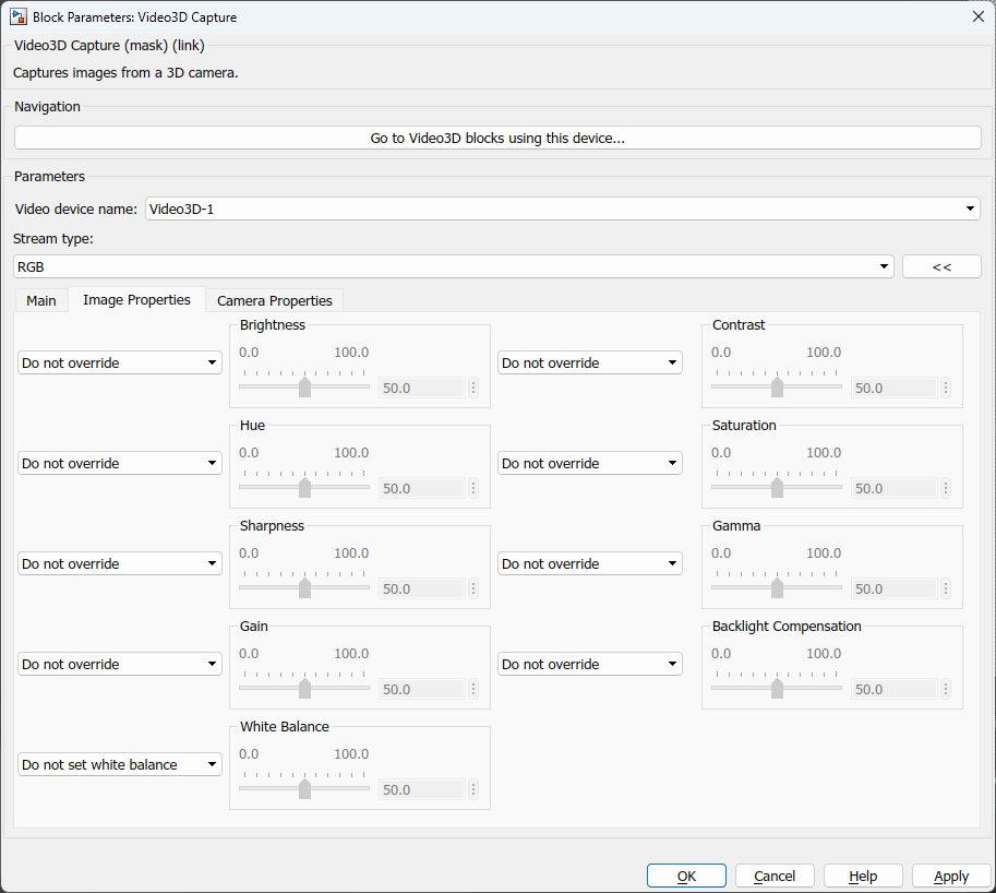
The Image Properties tab contains the settings related to the image output. This tab only applies when an actual device is being used, as opposed to a file.
Brightness Override
Set this option to Override using dialog to enable the video's brightness to be controlled via the Brightness parameter. Set this option to Override using input port to enable the video's brightness to be controlled via external input port, brt. If this option is set to Do not override then the video's brightness is not set.
Brightness (tunable online)
The brightness of the video, from 0 to 100% of the full range supported by the camera. This option is only enabled if the Brightness Override option is set to Override using dialog.
Contrast Override
Set this option to Override using dialog to enable the video's contrast to be controlled via the Contrast parameter. Set this option to Override using input port to enable the video's contrast to be controlled via external input port, con. If this option is set to Do not override then the video's contrast is not set.
Contrast (tunable online)
The contrast of the video, from 0 to 100% of the full range supported by the camera. This option is only enabled if the Contrast Override option is set to Override using dialog.
Hue Override
Set this option to Override using dialog to enable the video's hue to be controlled via the Hue parameter. Set this option to Override using input port to enable the video's hue to be controlled via external input port, hue. If this option is set to Do not override then the video's hue is not set.
Hue (tunable online)
The shade of colours of the video, from 0 to 100% of the full range supported by the camera. This option is only enabled if the Hue Override option is set to Override using dialog.
Saturation Override
Set this option to Override using dialog to enable the video's saturation to be controlled via the Saturation parameter. Set this option to Override using input port to enable the video's saturation to be controlled via external input port, sat. If this option is set to Do not override then the video's saturation is not set.
Saturation (tunable online)
The intensity of the colour relative to the brightness of the video, from 0 to 100% of the full range supported by the camera. This option is only enabled if the Saturation Override option is set to Override using dialog.
Sharpness Override
Set this option to Override using dialog to enable the video's sharpness to be controlled via the Sharpness parameter. Set this option to Override using input port to enable the video's sharpness to be controlled via external input port, shp. If this option is set to Do not override then the video's sharpness is not set.
Sharpness (tunable online)
The amount of details visible in the video, from 0 to 100% of the full range supported by the camera. This option is only enabled if the Sharpness Override option is set to Override using dialog.
Gamma Override
Set this option to Override using dialog to enable the video's gamma to be controlled via the Gamma parameter. Set this option to Override using input port to enable the video's gamma to be controlled via external input port, gam. If this option is set to Do not override then the video's gamma is not set.
Gamma (tunable online)
The non-linear operation in coding luminance values of the video, from 0 to 100% of the full range supported by the camera. This option is only enabled if the Gamma Override option is set to Override using dialog.
Gain Override
Set this option to Override using dialog to enable the video's gain to be controlled via the Gain parameter. Set this option to Override using input port to enable the video's gain to be controlled via external input port, gain. If this option is set to Do not override then the video's gain is not set.
Gain (tunable online)
The multiplier to apply to the RGB colour values of the video, from 0 to 100% of the full range supported by the camera. This option is only enabled if the Gain Override option is set to Override using dialog.
White Balance Override
Set this option to White balance via dialog to enable the video's white balance to be controlled via the White Balance parameter. Set this option to White balance via input port to enable the video's white balance to be controlled via external input port, wbl. Set this option to Automatic white balance to have the camera automatically determine the white balance. If this option is set to Do not set white balance then the video's white balance will not be set.
White Balance (tunable online)
The colour temperature of the video, from 0 to 100% of the full range supported by the camera. This option is only enabled if the White Balance Override option is set to White balance via dialog.
Backlight Compensation Override (tunable offline)
Set this option to Override using dialog to enable the video's backlight compensation to be controlled via the Backlight Compensation parameter. Set this option to Override using input port to enable the video's backlight compensation to be controlled via external input port, bck. If this option is set to Do not override then the video's backlight compensation is not set.
Backlight Compensation (tunable online)
The backlight compensation of the video, from 0 to 100% of the full range supported by the camera. This option is only enabled if the Backlight Compensation Override option is set to Override using dialog.
Camera Properties Pane
The Camera Properties pane of the dialog appears as follows:
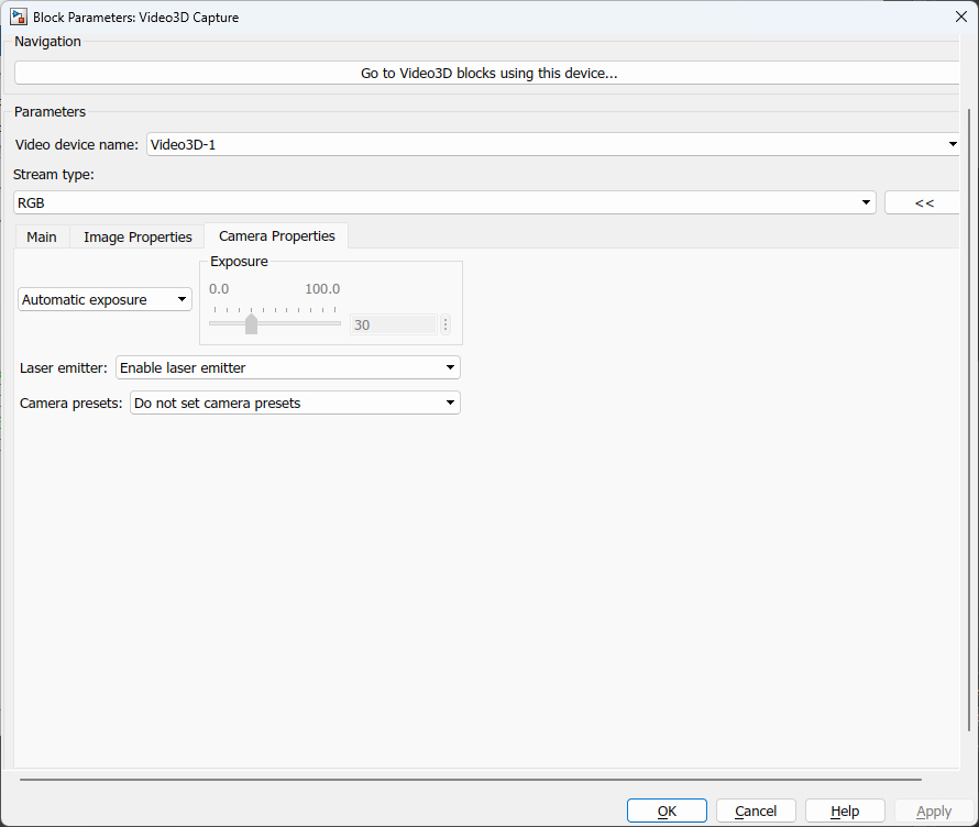
The Camera Properties tab contains the settings related to the camera hardware. This tab only applies when an actual device is being used, as opposed to a file.
Exposure Override
Set this option to Exposure via dialog to enable the video's exposure to be controlled via the Exposure parameter. Set this option to Exposure via input port to enable the video's exposure to be controlled via external input port, exp. Set this option to Automatic exposure to have the camera automatically determine the exposure. If this option is set to Do not set exposure then the video's exposure will not be set.
Exposure (tunable online)
The exposure of the video, from 0 to 100% of the full range supported by the camera. This option is only enabled if the Exposure Override option is set to Exposure via dialog.
Laser emitter (tunable offline)
Some cameras, such as the Intel RealSense R200 camera, contain an infrared laser emitter for illuminating the scene with a distinct pattern. When used outdoors, the laser emitter is generally not necessary because the infrared light from the sun illuminates the scene. Indoors, however, the laser emitter can be useful for providing the necessary illumination, as many light sources do not emit infrared. Since it emits a distinct pattern, it can also be helpful in determining the depth of uniform surfaces such as blank walls. Note however that the laser may show up in optical tracking systems that employ infrared cameras.
Set this option to Enable laser emitter to enable the laser emitter. Set the option to Disable laser emitter to disable the laser emitter. If this option is set to Do not set laser emitter then the laser emitter configuration is not set and will maintain its current value.
Camera presets (tunable offline)
Some cameras support predefined presets that tune the internal camera properties for different scenarios. For example, the Intel RealSense R200 camera uses a stochastic algorithm to match left and right stereoscopic images. It has different preset configuration which tune how many statistical outliers in the depth image are removed. If the R200 low outlier removal option is selected then it will provide depth information for more pixels, but the depth information may be less accurate. If the R200 high outlier removal option is chosen then it will only provide depth information for pixels in which it has more confidence in its depth estimation. Hence, there will be more black pixels in the scene, since a zero pixel value is used for a pixel when the depth cannot be determined for that pixel.
Targets
|
Target Name |
Compatible* |
Model Referencing |
Comments |
|---|---|---|---|
|
Yes |
Yes |
||
|
Yes |
Yes |
||
|
Yes |
Yes |
||
|
Yes |
Yes |
||
|
Yes |
Yes |
||
|
Yes |
Yes |
||
|
Yes |
Yes |
||
|
Yes |
Yes |
||
|
Yes |
Yes |
||
|
Yes |
Yes |
||
|
Yes |
Yes |
||
|
Yes |
Yes |
||
|
No |
No |
Not supported. |
|
|
No |
No |
Not supported. |
|
|
Rapid Simulation (RSIM) Target |
Yes |
Yes |
Fully supported. |
|
S-Function Target |
No |
N/A |
Old technology. Use model referencing instead. |
|
Normal simulation |
Yes |
Yes |
Fully supported. |
Copyright ©2026 Quanser Inc. This page was generated 2026-05-13. Submit feedback to Quanser about this page.
Link to this page.