

3ds Max X3D Plugin
The visualization blocks make it easy to assemble your animation scene, but you first need the content to display in your scene. QUARC includes a number of different meshes, textures, and scene files in the Quanser/QUARC/resources folder, but in many cases you will want to create textures and meshes that represent your specific system. Two tools are presently supported including Autodesk's 3ds Max (www.autodesk.com) versions 2008 to 2012, and the open source Blender (www.blender.org). Included with the installation of QUARC are x3d exporter plugins for both packages.
This help page covers the details of the 3ds Max plugin. If you would like information on the Blender plugin, please refer to the Blender x3d plugin help page.
Exporting from 3ds Max
| 3ds Max is commercial software available from Autodesk (www.autodesk.com). The plugin will only be installed if a supported copy of 3ds Max is found. If you install 3ds Max after installing QUARC, you can go to the Windows Control Panel, Add or Remove Programs (Programs And Features in Vista), find QUARC and click the Change button. When the install dialog opens select Repair and the installation will attempt to reinstall the plugin. |
The use of 3ds Max is beyond the scope of this help page, however, a few useful tips are included in the mesh construction considerations section. You will need to refer to the documentation included with 3ds Max or online tutorials for modelling techniques. This page will focus on the details of exporting meshes for use in your visualizations.
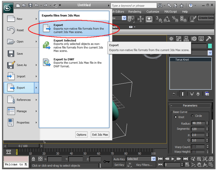
After you have created your mesh, go to the File menu (Application menu in 3ds Max 2011) and export (to export all objects), or export selected (to export just the objects currently selected) to export your scene meshes.
At the next dialog, change the Save as type to "Quanser X3D", and enter a filename.
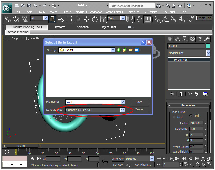
This name will be used as a prefix to the mesh names.
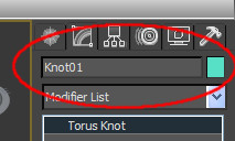
It will also be used as the scene file if that option is selected on the next dialog. Click the Save button to continue to the options dialog.
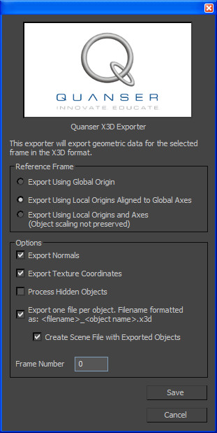
The following options are available:
Export Using Global Origin
All objects will be exported with their local origin positioned the global origin. All rotations, translations, scaling, and other modifications will be preserved. This is useful for loading static objects since they will be then loaded to the origin by default in a scene file.
Export Using Local Origins Aligned to the Global Axes
Objects will be exported about the local origin, but the axes will be aligned to the global axes. This will effectively preserve all transformations except translation (the object will move to the global origin by default). To see what the origin and axes of the object are, you need to set your reference frame to the world coordinate system, and change your working pivot to "Use Pivot Center". These two options can be set on the toolbar as shown below:
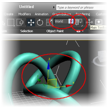
| You can use the "Affect Pivot Only" under the hierarchy tab to move the local origin of a mesh to a more convenient location. |
Export Using Local Origins and Axes
Objects will be exported about the local origin. This will eliminate any translation, rotation and scale applied at the object level. Due to the relationship of scale and rotation in a transformation matrix, it is not always possible to preserve the scale independently of the rotation. If you want to scale an object, but still have it export about the local axes, add an "Edit Mesh" modifier and scale the object at the vertex, edge, face, or polygon level (therefore modifying the underlying mesh geometry rather than its transformation). To see what the origin and axes of the object are, you need to set your reference frame to the local coordinate system, and change your working pivot to "Use Pivot Center". These two options can be set on the toolbar as shown below:
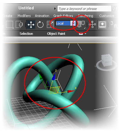
| You can use the "Affect Pivot Only" under the hierarchy tab to move and rotate the local origin of a mesh to a more convenient location. |
Export Normals
Normals are used to calculate the shading on each mesh as a function of the position of the light sources. Although one typically thinks of normals as being a function of a face or surface, in OpenGL they are associated with the vertices as that is where the lighting calculations are done. If two adjacent faces are part of the same smoothing group, then they will share a single vertex with a normal that is an average of the two face normals. If two adjacent faces are in different smoothing groups, then the vertex will be duplicated and each vertex will be assigned a normal corresponding to the attached face. If the vertex of a face does not have an adjacent face, then the vertex normal will be the same as the face normal. It is possible to override the default normal calculations by adding an Edit Normal modifier to the stack. If at least one normal is explicitly specified, then the results from the Edit Normal modifier will be used instead of recalculating the normals. See the mesh construction considerations section for more details.
Export Texture Coordinates
Texture coordinates define how to wrap a bitmap texture onto the mesh. If a texture is not attached to a mesh in the object pool of the scene file then the texture coordinates will be ignored. The primary reason that you might not want to export the texture coordinates would be to reduce your x3d file size.
Process Hidden Objects
If you are exporting your entire scene, then you have the option of also processing meshes that are not visible. By leaving this unchecked, you can selectively export your scene in terms of what is visible instead of explicitly selecting all the meshes you wish to export and using the Export Selected option from the File menu.
Separate files for each object
Checking this option will append the name that you entered in the Save As box with the mesh object name. Using this option will overwrite any existing files without confirmation. When checked, if multiple objects are selected, multiple files will be produced. If this is not checked and multiple objects are selected, a single file containing all the meshes will be produced. Note, however, the Visualization Initialize block will only use the first mesh found.
If you would like multiple mesh objects to behave as a single body in your visualization without creating parent-child relationships between each of them, then you can first combine them into a single mesh before exporting. Add an "Edit Mesh" modifier to one of your objects, the use the "Attach Mesh" function to amalgamate additional meshes into a single object.
Create Scene File with Exported Objects
In addition to exporting the meshes, selecting this option will also create a scene file that references the exported objects using the selected filename appended with the xml extension. If a mesh uses a texture with a diffuse bitmap, the bitmap will be automatically added to the texture pool and referenced by the object.
Although all reference frame modes are supported, you typically want to use Export Using Local Origins Aligned to Global Axes with this option. This will effectively create a scene file with all meshes retaining their local origins, but offset to their current locations using the initial position in the scene file. The each mesh's current scale and rotation will be taken from their current state to be [1 1 1] and [0 0 0] respectively.
One particularly powerful feature of exporting the scene file from within 3ds Max is support for the hierarchical links. Using the link and unlink tools:
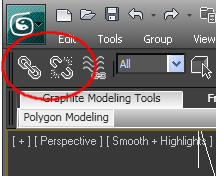
You can create parent-child hierarchy directly within 3ds Max and test the joint motions before exporting. All the objects will be offset to the correct relative locations to the parent objects. Only the local origin modes are supported. If you export using the global origin, all links will be ignored.
You can also setup lighting within the scene. Only standard omni directional lights are supported.
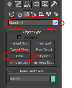
Other light sources will be exported as dummy actors.
Frame Number
If your 3ds Max file includes animation, then you select which animation frame you wish to extract the mesh files from. It will default to the current frame that your animation slider is on.
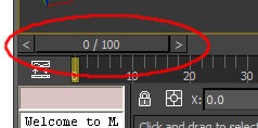
Clicking the button will then export your meshes to the specified x3d files. If you wish to convert your x3d files to the q3d format, you can use the included qc_convert_to_q3d Matlab function. Since the q3d format is binary, the files can be significantly smaller than the ASCII x3d files. No tools are provided to change from q3d back to x3d or any other format, so this can be beneficial for distributing 3d models for viewing, but where you do not want someone to be able to put it in another CAD program.
Mesh Construction Considerations
Render Priorities
If you are constructing a user interface element such as a dial in front of a numbered face using two bitmaps mapped onto rectangles, you will want to separate them by some small distance. When you go to export them, you can move them both back to the origin as described above, then reconstruct their respective offsets in the visualization initialize block.
Alternatively, you can keep their current placement (assuming this is compatible the with rotations, translations, and scaling you want to use to animate them) so they will all share the same position. If the applied bitmaps are tif or jpg, then loading all the meshes will result in the same offsets you had in 3ds Max. However, if the textures are bmp or png and you are making use of sections of the bitmap being transparent, then you may see some render priority fighting in which case you will need to set the render priorities such that the elements are rendered from back to front to preserve the intended transparency.
Another example of this is drawing a box within a box. To create the appearance of a solid prism where you can see the back faces through the front faces, you first draw one box, make a copy, and invert the normals of the copy. Exporting both boxes will result in them both sharing the same origin. Once you set their opacity to a value less than one, there is the potential for render priority fighting again. In this case, you want to set the render priorities such that the "inner face" box is always rendered first so the "outer face" box does not occlude the inner edges.
Since both boxes are fixed relative to one another, using the edit mesh modifier, you can attach the outer face box to the inner face box. The order in which 3ds Max stores the vertices and faces (and therefore the order in which they are exported) is related to the order in which faces are added to a given mesh. For a mesh with many transparent or semi-transparent faces, it may require some experimentation to achieve the render order desired from every angle, or you can export several pieces and connect them together using a hierarchy in the scene file.
Scene Scale
The default scene in the Visualization blocks places the camera at a position of [-5 0 0], looking at the origin. If you are not constrained to using particular dimensions, try to fit your mesh within a unit box centered about the origin. That way, when you load a mesh into your visualization in the default location, with the default camera position, you should see your directly in front of you.
Normals
There are instances where you want something made up of sections to appear as a single smooth surface. The terrain in the airplane demo for instance is made up of a grid of 9 repeating terrain sections. To avoid making the seams apparent, it isn't enough to make sure that the position of the edge vertices all match, the normals must also be identical. A simpler example of this is creating a sphere in 3ds Max, then splitting it into two parts.
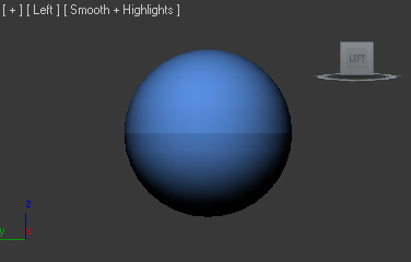
The seam is very apparent because although the position of all the vertices match at the seam, the normals were recalculated on the assumption that it was no longer a continuous surface. This is made more visible by adding an Edit Normals modifier to the stack. It would be expected that cutting the sphere at the equator should result in normals that are also in the plane of the equator, but that is no longer the case because the faces just north and south of the equator are not quite perpendicular to the equatorial plane.
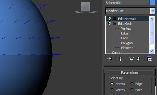
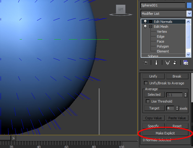
To solve this problem, let's backup to the complete sphere again before it is separated and add an Edit Normals modifier to the stack. As expected, the normals at the equator are now in the equatorial plane. Select the normals at the equator (or optionally all the normals) and click the button "Make Explicit". After deselecting the normals, the successful application of making the normals explicit should make those normals a different color (green in the image below).
To split the sphere now, add an Edit Mesh modifier to the stack, then duplicate the object and delete the northern faces on one copy, and the southern faces on the other. Do not just Detach half of the faces or the explicit normal information will be lost. The result as shown below is the appearance of a continuous surface even though the sphere has been divided into two meshes.
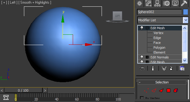
Mirroring
If you need to mirror a mesh in 3ds Max, it is recommended that you use the mirroring on the modifier stack instead of the mirroring from the Tools menu. The mirroring from the Tools menu mirrors both the normals as well as the geometry that, depending on your X3D export options, will result in geometry that looks inside-out. This can be corrected by either applying a Normal modifier to the stack and selecting "Flip Normals" which will make it appear inverted in 3ds Max, or select a mesh that is in the correct orientation and "Attach" the inverted mesh from the Edit Mesh modifier on the stack. The original mesh can be then be detached again and the face orientation will now be correct when it is exported. Note that this second method will not make any visible change in 3ds Max, but it can be used to correct previously created meshes that have inverted normals.

Copyright ©2025 Quanser Inc. This page was generated 2025-11-01. Submit feedback to Quanser about this page.
Link to this page.