
Blender X3D Plugin
The visualization blocks make it easy to assemble your animation scene, but you first need the content to display in your scene. QUARC includes a number of differ meshes, textures, and scene files in the Quanser/QUARC/resources folder, but in many cases you will want to create textures and meshes that represent your specific system. Two tools are presently supported including Autodesk's 3ds Max (www.autodesk.com), and the open source Blender version 2.49b (www.blender.org). Included with the installation of QUARC are x3d exporter plugins for both packages.
This help page covers the details of the Blender plugin. If you would like information on the 3ds Max plugin, please refer to the 3ds Max plugin help page.
Exporting from Blender
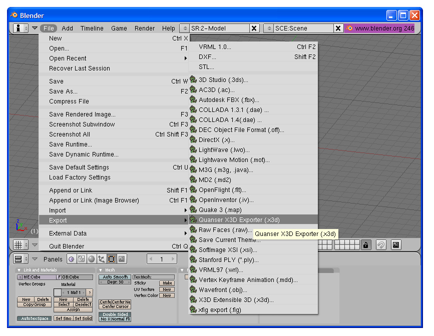
| Blender is open source software available from www.blender.org. If you already have Blender installed on your system and it was installed via the Windows installer (as opposed to using the .zip installation method), then QUARC will attempted to automatically install the plugin. If you installed Blender using the .zip method or installed it after QUARC was installed, you can manually install the exporter by copying quanser_x3d_export.py from the Quanser/Quarc/blender/.blender/scripts to your corresponding Blender/.blender/scripts folder. It will now show up under the File/Export menu as Quanser X3D Exporter. |
The use of Blender is beyond the scope of this help page, however, a few useful tips are included in the mesh construction considerations section. You will need to refer to the Blender documentation or online tutorials for modeling techniques. This page will focus on the details of exporting meshes for use in your visualizations.
All meshes in Blender will be exported about the global origin. This means for parts such as a robot arm, you will want to relocate each part to the global origin before exporting and to make things easier for manipulating with the visualization blocks, you typically want to locate the part origin at the center of a joint closest to the base joint.
After you have created your mesh, go to the File menu, export, and selected the Quanser x3d exporter. Although Blender includes an x3d plugin, it does not reproduce smooth surfaces.
This will bring up a dialog as shown below.
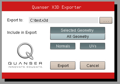
The following options are available:
Export Normals
Normals are used to calculate the shading on each mesh as a function of the position of the light sources. Although one typically things of normals as being a function of a face or surface, in OpenGL they are associated with the vertices as that is where the lighting calculations are done. If two adjacent faces are smooth, then they will share a single vertex with a normal that is an average of the two face normals. If at least one of two adjacent faces are not marked as smooth, then the vertices will be duplicated and each vertex will be assigned a normal corresponding to the attached face.
UV's
Texture coordinates (also known as UV's or UVW's) define how to wrap a bitmap texture onto the mesh. If a texture is not attached to a mesh in the object pool of the scene file then the texture coordinates will be ignored. The primary reason that you might not want to export the texture coordinates would be to reduce your x3d file size. Even with this option checked, texture coordinates will only be exported if they are available for the selected mesh(s).
Clicking the button will then export your mesh to the specified x3d file. If you wish to convert your x3d files to the q3d format, you can use the included qc_convert_to_q3d Matlab function. Since the q3d format is binary, the files can be significantly smaller than the ASCII x3d files. No tools are provided to change from q3d back to x3d or any other format, so this can be beneficial for distributing 3d models for viewing, but where you do not want someone to be able to put it in another CAD program.
Mesh Construction Considerations
If you are constructing a user interface element such as a dial in front of a numbered face using two bitmaps mapped onto rectangles, you will want to separate them by some small distance. When you go to export them, you can move them both back to the origin as described above, then reconstruct their respective offsets in the Visualization Initialize block.
Alternatively, you can keep their current placement (assuming this is compatible with rotations, translations, and scaling your want to use to animate them) so they will all share the same position. If the applied bitmaps are tif or jpg, then loading all the meshes will result in the same offsets you had in Blender. However, if the textures are bmp or png and you are making use of sections of the bitmap being transparent, then you may see some render priority fighting in which case you will need to set the render priorities such that the elements are rendered from back to front to preserve the intended transparency.
Another example of this is drawing a box within a box. To create the appearance of a solid prism where you can see the back faces through the front faces, you first draw one box, make a copy, and invert the normals of the copy. Exporting both boxes will result in them both sharing the same origin. Once you set their opacity to a value less than one, there is the potential for render priority fighting again. In this case, you want to set the render priorities such that the "inner face" box is always rendered first so the "outer face" box does not occlude the inner edges.
Finally, the default scene in the Visualization blocks places the camera at a position of [-5 0 0], looking at the origin. If you are not constrained to using particular dimensions, try to fit your mesh within a unit box centered about the origin. That way, when you load a mesh into your visualization in the default location, with the default camera position, you should see your directly in front of you.
Copyright ©2026 Quanser Inc. This page was generated 2026-05-13. Submit feedback to Quanser about this page.
Link to this page.
