
Icon Conventions
In order to provide a consistent user experience and breed familiarity with the functionality of the Quanser Rapid Control Prototyping (RCP) Toolkit, Quanser has implemented a set of conventions in the design of the icons for the VIs and functions in the RCP Toolkit.
The VIs and functions in the RCP Toolkit may be classified into three broad categories:
General VIs
General VIs may be used anywhere in a LabVIEW block diagram. They may be used inside a Control & Simulation
(CD & Sim) Loop as well, but are not restricted to the CD & Sim loop. VIs in this broad category are
represented with a red background:
![]()
Control Loop VIs
Control Loop VIs are intended for use in a Control & Simulation (CD & Sim) Loop. When they are used outside
a CD & Sim Loop they have their own sampling period and one integration step is performed each time the block is
executed. VIs in this category are represented with a blue background:
![]()
The Control Loop VIs may be further subdivided into two categories - those that read and those that write. For example, the CL HIL Read VI reads from a hardware-in-the-loop (HIL) or data acquisition card. The CL HIL Write VI writes to a HIL card. Within both subcategories, there are consistent glyphs used to represent different kinds of I/O channels.
Read VIs
VIs that read from hardware or a communication channel contain reading glasses in their icon, as depicted below:

Write VIs
VIs that write to hardware or a communication channel contain a pencil in their icon, as illustrated below:

Standard Glyphs
The Quanser Hardware-in-the-Loop (HIL) API supports five different standard types of I/O channels:
There is also a Quanser Stream API for utilizing communication channels:
Each type of channel has an associated glyph to make it easy to identify the purpose of a VI involving I/O.
Analog I/O
Analog I/O is used for reading or writing analog signals, such as voltages and currents. Analog signals are denoted by the sinusoidal glyph shown below:
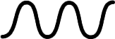
Analog signals are represented as double-precision floating-point values since they are generally real values within a predefined range.
Digital I/O
Digital I/O is used for reading or writing digital signals, such as switches, buttons and enable lines. Digital signals are denoted by a sequence of zeroes and ones as illustrated below:

Digital signals are represented as boolean values since they are either on or off at any point in time.
Encoder Input
Encoder inputs are used for reading quadrature encoders (or count and direction signals). Since encoders require both A and B lines per encoder, the glyph used for encoders depicts two digital waveforms that are 90 degrees out of phase, just like the A and B signals of a quadrature encoder.

Since encoders maintain an internal counter, encoder inputs output the value of the counter. This value is represented as a 32-bit signed integer.
PWM Output
Pulse-width modulated (PWM) signals are used for writing to PWM outputs. A PWM output involves modulating the duty cycle of an output square wave in order to achieve an average voltage (or current). PWM signals are denoted by a digital waveform with varying duty cycle, as demonstrated below:

PWM signals are represented as double-precision floating-point values since they are generally real values within a predefined range.
Other I/O
Any type of signal which does not fit in the other standard categories is classified as an "other" signal. There are predefined channels for a variety of common signals, such as encoder velocities. Since "other" channels are different from the rest, the glyph used to represent them is a sawtooth waveform, as shown below:
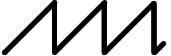
Other signals are represented as double-precision floating-point values.
Communication I/O
The Communication I/O framework supplies a single framework to handle all RCP-supported communication protocols. Communication signals are denoted by a propagating wave as illustrated below:

Communication signals are represented as values of any data type.
Utility VIs
Utility VIs may be used anywhere in a LabVIEW block diagram. They are a miscellaneous set of VIs that are useful in a variety of contexts. Such VIs are denoted with a yellow background:
![]()
Copyright © Quanser Inc. This page was generated 2024-11-15. Submit feedback to Quanser about this page.
Link to this page.